
pwm rectifier power controller

A PWM (Pulse Width Modulation) rectifier power controller is a sophisticated electronic circuit designed to convert alternating current (AC) to direct current (DC) while maintaining high efficiency and low harmonic distortion. This type of power supply utilizes PWM techniques to modulate the width of the pulses in the output waveform, allowing for precise control over the output voltage and current.
The circuit typically consists of several key components, including a rectifier bridge, PWM controller, filter capacitors, and an output load. The rectifier bridge, usually composed of diodes, converts the incoming AC voltage to pulsating DC. The PWM controller then regulates this pulsating DC by adjusting the duty cycle of the output signal, which in turn controls the average voltage delivered to the load.
In a typical configuration, the PWM controller receives feedback from the output voltage or current, allowing it to adjust the PWM signal dynamically. This feedback loop ensures that the output remains stable under varying load conditions. Filter capacitors are employed to smooth the pulsating DC output, reducing ripple and providing a more stable DC voltage to the load.
The design of the PWM rectifier power controller circuit can also include additional features such as over-voltage protection, under-voltage lockout, and thermal protection to enhance reliability and safety. The overall efficiency of this power supply design can reach upwards of 95%, making it suitable for applications requiring high performance and energy efficiency.
This power supply is commonly used in various applications, including renewable energy systems, electric vehicles, and industrial automation, where precise control and high efficiency are paramount. The circuit diagram associated with this power supply provides a visual representation of the interconnections and functionality of the components, facilitating better understanding and implementation of the design.PWM Rectifier power controller power supply. Go to that page to read the explanation about above power supply related circuit diagram. 🔗 External reference
Related Circuits
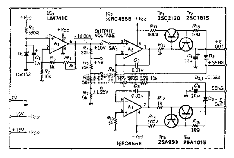
The maximum input voltage is 10V. An operational amplifier (op-amp) is used to provide a reference voltage of 10V, with its stability primarily determined by the characteristics of a temperature-compensated Zener diode (IS2192). The Zener voltage (Vz) can be...
Powering up twin digital Sony DSC-V1 cameras simultaneously can achieve remarkable synchronization within milliseconds. This is accomplished through the use of dual Sony wired remotes that short the ACC port LANC signal conductor to the ACC port ground. Further...
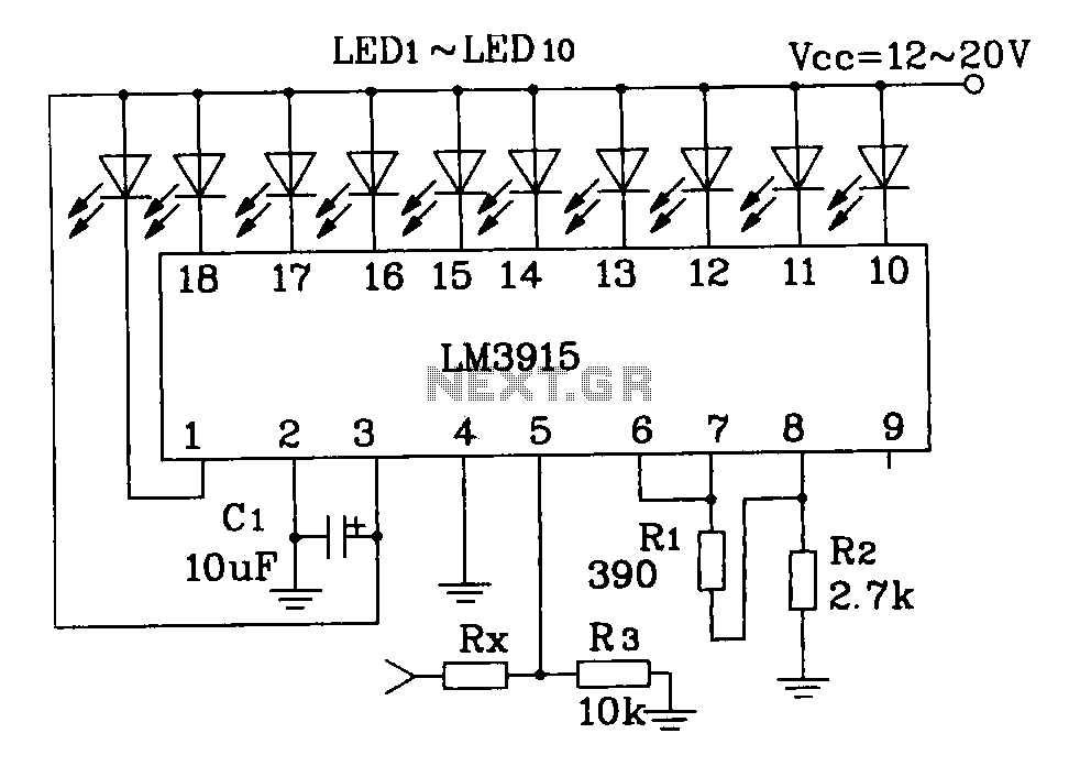
This document describes a simple LM3915 audio power meter circuit diagram. It notes that if the internal resistance of the speaker is 4 ohms, a resistor value of 10k ohms should be used for Rx. For an 8-ohm speaker,...
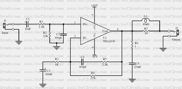
This simple 10 watts audio power amplifier is designed for home-brewed purpose. It is based on an Audio Power Amplifier IC that is called TDA2030. It is a monolithic integrated circuit in Pentawatt package, intended for use as a...

A battery-powered portable unit suitable for all types of televisions. This low-cost project allows audio reproduction from a TV without disturbing others. This battery-powered portable audio unit is designed to provide a convenient solution for reproducing television audio discreetly. The...
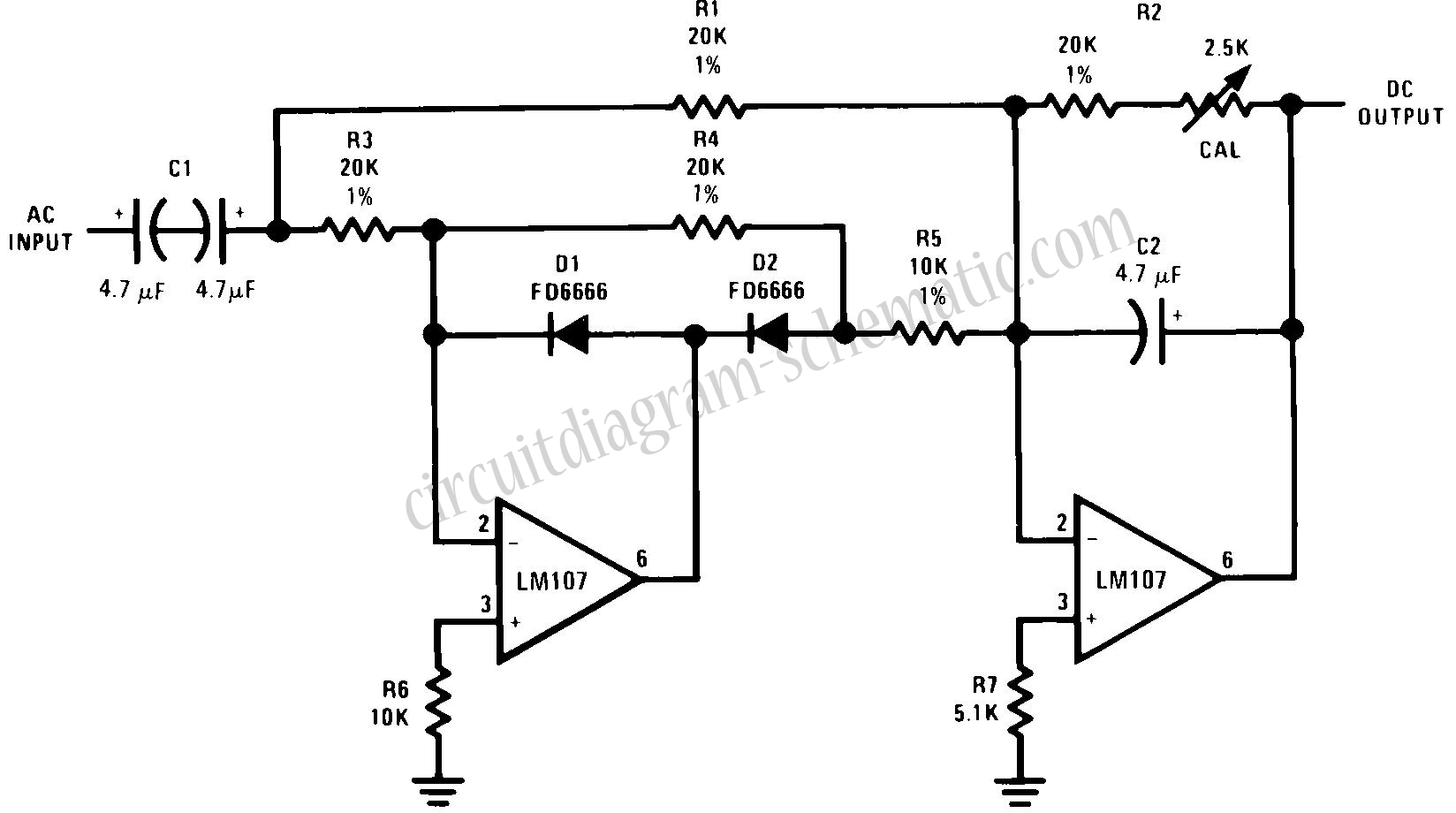
This circuit is an RMS-calibrated AC voltmeter that provides average readings. Removing capacitor C2 eliminates the averaging function, resulting in a precision full-wave rectifier, while removing capacitor C1 transforms the circuit into an absolute value generator. The operation of...