
ac TRIAC dimmer circuit design help (resistive load)
")
The design of the light-dimming control system will involve several key elements to ensure effective operation and safety. The primary component in this application is a solid-state relay (SSR) or a triac-based dimmer circuit, which will allow for the control of the AC power supplied to the heat lamp. The SSR or triac should be rated for at least 4A to handle the maximum surge current that may occur during the initial switch-on phase, which can be significantly higher than the steady-state current. The selection of the relay must also consider the operational voltage, which in this case is 240V AC.
Incorporating a zero-cross detection circuit can enhance the performance of the dimming control by ensuring that the switching of the relay occurs at the point where the AC voltage crosses zero, thereby minimizing electrical noise and reducing stress on the relay. This is particularly important in applications involving resistive loads like heat lamps, as it extends the lifespan of the switching component.
The microprocessor, based on the 8051 architecture, will control the dimming operation through pulse-width modulation (PWM) or phase control techniques. The PWM signal can be generated by the microprocessor to adjust the average power delivered to the lamp, effectively controlling the heat output. The microprocessor should also be programmed to monitor the current flowing through the heat lamp to prevent exceeding the rated specifications and to ensure safe operation.
To achieve accurate measurements of the current, a current sensing resistor or a Hall effect sensor can be implemented in series with the load. This will provide feedback to the microprocessor, allowing it to adjust the PWM signal dynamically based on the actual current draw of the heat lamp. Additionally, implementing overcurrent protection circuitry, such as a fuse or a circuit breaker rated appropriately for the application, will enhance safety.
Finally, the integration of RF circuitry will allow for remote control and monitoring of the heat lamp's operation, providing flexibility and enhancing user convenience within the wireless sensor network. The system design should also include considerations for heat dissipation from electronic components, ensuring that the overall system remains within safe operating temperatures.Making a light-dimming control system for a 240V heat lamp dissipating around 250W. I need to adjust the heat output on the lamp by control from a microprocessor. I`m developing on an 8051-based SoC with RF circuitry and some sensors and actuators. Basically it`s a node in a wireless sensor network. I`ve left all other components out. I`m mostly a software guy, so I might need some help here. Pardon my lingo and if I raise fundamental questions, I don`t have a lot of experience with this. A max surge-current rating of 4A would leave some overhead I would assume, but I`m not sure how much I need. I am assuming a switch-on from cold could draw a lot of current - should I instrument to be sure I don`t have any data on the heat lamp other than its rated for 250W max.
🔗 External reference
Related Circuits
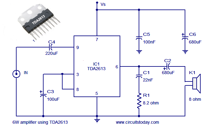
A simple and easy-to-build Hi-Fi audio power amplifier circuit is presented here. This 6-watt Hi-Fi audio amplifier circuit utilizes the TDA2613 integrated circuit (IC). The circuit design employs the TDA2613, which is a high-performance audio amplifier IC known for its efficiency...
This caller ID circuit utilizes the Motorola MG145447 IC chip. The service must be available from your local phone company for this circuit to function properly. The caller ID circuit based on the Motorola MG145447 IC chip is designed to...

This article demonstrates how to create a simple yet effective static electricity generator. This device enables the user to carry a constant static charge on their body and discharge it onto anything grounded or of opposite polarity. The generated...
Under the loading condition of the resistance, the output voltage (Uo) variable range is from 30V to 36V, with a maximum output current (Imax) of 2A. When the input voltage (U2) changes from 15V to 21V, the voltage regulation...

The module costs £38.00, and the transducer costs an additional £17.00. The Polaroid module effectively performs its intended function, which requires a certain range; however, it is not designed to serve as the vision system for a small robot....

This circuit protects a PC by requiring a password to boot. After three unsuccessful attempts, the computer must undergo a cold reboot before the password can be attempted again. Software for this system is available; consult the reference for...