
Q-Meter

Every inductor coil possesses a certain amount of resistance, and it is essential for the coil to have the lowest possible resistance. The ratio of inductive reactance to the effective resistance of the coil is referred to as the quality factor, or Q-factor, of the coil. A high Q value is desirable as it indicates high inductive reactance and low resistance. Conversely, a low Q value suggests that the resistance component is relatively high, leading to significant power loss. The effective resistance of the coil differs from its DC resistance due to eddy currents and skin effects, varying in a complex manner with frequency. Consequently, Q is seldom calculated simply by determining R and L. One method for determining Q is through the use of an inductance bridge; however, such bridge circuits often lack accuracy when Q is high. Therefore, specialized meters are employed for precise Q measurement. The Q-meter is an instrument designed to measure the Q-factor of coils and assess the electrical properties of coils and capacitors. This instrument operates on the principle of series resonance; at the resonant condition of an AC series circuit, the voltage across the capacitor equals the applied voltage multiplied by the circuit's Q. If the voltage across the circuit is constant, a voltmeter connected across the capacitor can be calibrated to directly indicate Q. A wide-range oscillator, with a frequency range from 50 kHz to 50 MHz, serves as the power supply for the circuit. The output of the oscillator is shorted by a low-value resistance, Rsh, typically around 0.02 ohms, introducing negligible resistance into the oscillatory circuit and acting as a voltage source with minimal internal resistance. The voltage across the low-value shunt resistance Rsh, denoted as V, is measured using a thermocouple meter, while the voltage across the capacitor, Vc, is measured with an electronic voltmeter. For measurement purposes, the unknown coil is connected to the test terminals of the instrument, and the circuit is tuned to resonance by either adjusting the oscillator frequency or varying the resonating capacitor C. Voltage readings across capacitor C and shunt resistance Rsh are taken, allowing for the determination of the coil's Q-factor.
The Q-factor is a critical parameter in the design and analysis of inductive components, as it provides insight into the efficiency of the coil in energy storage and transfer. High Q-factor inductors are essential in applications such as RF circuits, where losses must be minimized to maintain signal integrity. The measurement process using a Q-meter involves careful calibration and adjustment to ensure accurate readings, particularly at high frequencies where parasitic effects can significantly influence performance. The choice of a low-value shunt resistor is vital, as it minimizes the impact on the oscillatory circuit, allowing for precise voltage measurements that are crucial for calculating the Q-factor accurately. Additionally, the use of a thermocouple meter for measuring the voltage across Rsh ensures that thermal effects do not compromise the accuracy of the measurement. Overall, understanding the Q-factor and its implications on coil performance is essential for engineers designing high-frequency circuits and optimizing inductive components for various applications.We know that every inductor coil has a certain amount of resistance and the coil should have lowest possible resistance. The ratio of the inductive reactance to the effective resistance of the coil is called the quality factor or Q-factor of the coil.
A high value of Q is always desirable as it means high inductive reactance and low resistance. Alow value of Q indicates that the resistance component is relatively high and so there is a comparatively large loss of power. The effective resistance of the coil differs from its dc resistance because of eddy current and skin effects and varies in a highly complex manner with the frequency.
For this reason Q is rarely computed by determination of R and L. One possible way for determination of Q is by using the inductance bridge but such bridge circuits are rarely capable of giving accurate measurements, when Q is high. So special meters are used for determination of Q accurately. The Q-meter is an instrument designed for the measurement of Q-factor of the coil as well as for the measurement of electrical properties of coils and capacitors.
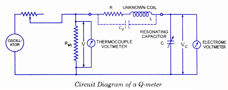
-This instru ment operates on the principle of series resonance i. e. at resonate condition of an ac series circuit voltage across the capacitor is equal to the applied voltage times of Q of the circuit. If the voltage applied across the circuit is kept-constant then voltmeter connected across the capacitor can be calibrated to indicate Q directly.
A wide-range os cillator with frequency range from 50 kHz to 50 MHz is used as a power supply to the cir cuit. The output of the oscillator is shorted by a low-value resistance, Rsh usually of the or der of 0. 02 ohm. So it in troduces almost no resistance into the oscillatory circuit and represents a voltage source with a very small or of almost negligible internal resistance.
The voltage across the low-value shunt resistance Rsh, V is measured by a thermo-couple meter and the voltage across the capacitor, Vc is measured by an electronic voltmeter. For carrying out the measurement, the unknown coil is connected to the test termi nals of the instrument, and the circuit is tuned to resonance either by varying the fre quency of the oscillator or by varying the resonating capacitor C.
Readings of voltages across capacitor C and shunt resistance Rsh are obtained and Q-factor of the coil is deter mined as follows : 🔗 External reference
The Q-factor is a critical parameter in the design and analysis of inductive components, as it provides insight into the efficiency of the coil in energy storage and transfer. High Q-factor inductors are essential in applications such as RF circuits, where losses must be minimized to maintain signal integrity. The measurement process using a Q-meter involves careful calibration and adjustment to ensure accurate readings, particularly at high frequencies where parasitic effects can significantly influence performance. The choice of a low-value shunt resistor is vital, as it minimizes the impact on the oscillatory circuit, allowing for precise voltage measurements that are crucial for calculating the Q-factor accurately. Additionally, the use of a thermocouple meter for measuring the voltage across Rsh ensures that thermal effects do not compromise the accuracy of the measurement. Overall, understanding the Q-factor and its implications on coil performance is essential for engineers designing high-frequency circuits and optimizing inductive components for various applications.We know that every inductor coil has a certain amount of resistance and the coil should have lowest possible resistance. The ratio of the inductive reactance to the effective resistance of the coil is called the quality factor or Q-factor of the coil.
A high value of Q is always desirable as it means high inductive reactance and low resistance. Alow value of Q indicates that the resistance component is relatively high and so there is a comparatively large loss of power. The effective resistance of the coil differs from its dc resistance because of eddy current and skin effects and varies in a highly complex manner with the frequency.
For this reason Q is rarely computed by determination of R and L. One possible way for determination of Q is by using the inductance bridge but such bridge circuits are rarely capable of giving accurate measurements, when Q is high. So special meters are used for determination of Q accurately. The Q-meter is an instrument designed for the measurement of Q-factor of the coil as well as for the measurement of electrical properties of coils and capacitors.
-This instru ment operates on the principle of series resonance i. e. at resonate condition of an ac series circuit voltage across the capacitor is equal to the applied voltage times of Q of the circuit. If the voltage applied across the circuit is kept-constant then voltmeter connected across the capacitor can be calibrated to indicate Q directly.
A wide-range os cillator with frequency range from 50 kHz to 50 MHz is used as a power supply to the cir cuit. The output of the oscillator is shorted by a low-value resistance, Rsh usually of the or der of 0. 02 ohm. So it in troduces almost no resistance into the oscillatory circuit and represents a voltage source with a very small or of almost negligible internal resistance.
The voltage across the low-value shunt resistance Rsh, V is measured by a thermo-couple meter and the voltage across the capacitor, Vc is measured by an electronic voltmeter. For carrying out the measurement, the unknown coil is connected to the test termi nals of the instrument, and the circuit is tuned to resonance either by varying the fre quency of the oscillator or by varying the resonating capacitor C.
Readings of voltages across capacitor C and shunt resistance Rsh are obtained and Q-factor of the coil is deter mined as follows : 🔗 External reference
Related Circuits
Every inductor coil possesses a certain amount of resistance, and it is essential for the coil to have the lowest possible resistance. The quality factor, or Q-factor, of the coil is the ratio of the inductive reactance to the...