
Q-Multiplying Loop Antenna

The circuit described is intended for use with a 4-foot square loop antenna, which is a common choice for medium wave (MW) radio reception, particularly in applications requiring long-distance signal capture. The loop antenna operates on the principle of electromagnetic induction, where the loop's dimensions are optimized to resonate at medium wave frequencies, typically ranging from 530 kHz to 1700 kHz.
The schematic likely includes components such as a tuning capacitor to adjust the resonant frequency of the loop, a matching transformer to efficiently couple the antenna to the receiver, and possibly an amplifier stage to boost weak signals. The tuning capacitor allows for fine adjustments to be made to the loop's resonant frequency, ensuring optimal reception of desired signals while minimizing interference from other sources.
Additionally, the circuit may incorporate a low-noise amplifier (LNA) to improve the signal-to-noise ratio, which is crucial for long-distance reception. The LNA should be designed to operate within the frequency range of interest and be placed as close to the antenna as possible to reduce losses.
Power supply considerations must also be addressed, ensuring that any active components receive a stable voltage without introducing noise into the system. Bypass capacitors may be included to filter out high-frequency noise from the power supply.
Overall, the design aims to maximize the effectiveness of the 4-foot square loop antenna in capturing distant medium wave signals while minimizing noise and interference, resulting in clearer audio output for the end-user.This circuit is designed to be used in conjunction with the standard 4 foot square loop used in MW for long distance reception. 🔗 External reference
Related Circuits
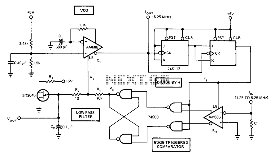
A circuit diagram of a phase-locked loop utilizes an AM686 latched comparator as a voltage-controlled oscillator, along with a TTL latch connected to generate edge-triggered comparators. The VCO and its comparison with the low-pass filter consisting of R1, R2,...
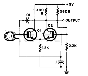
L1 is a loop consisting of 10 to 20 turns of insulated wire with a diameter ranging from 4 inches to 4 feet. The oscillator frequency, which operates between 7 to 30 MHz, varies significantly when an individual approaches...
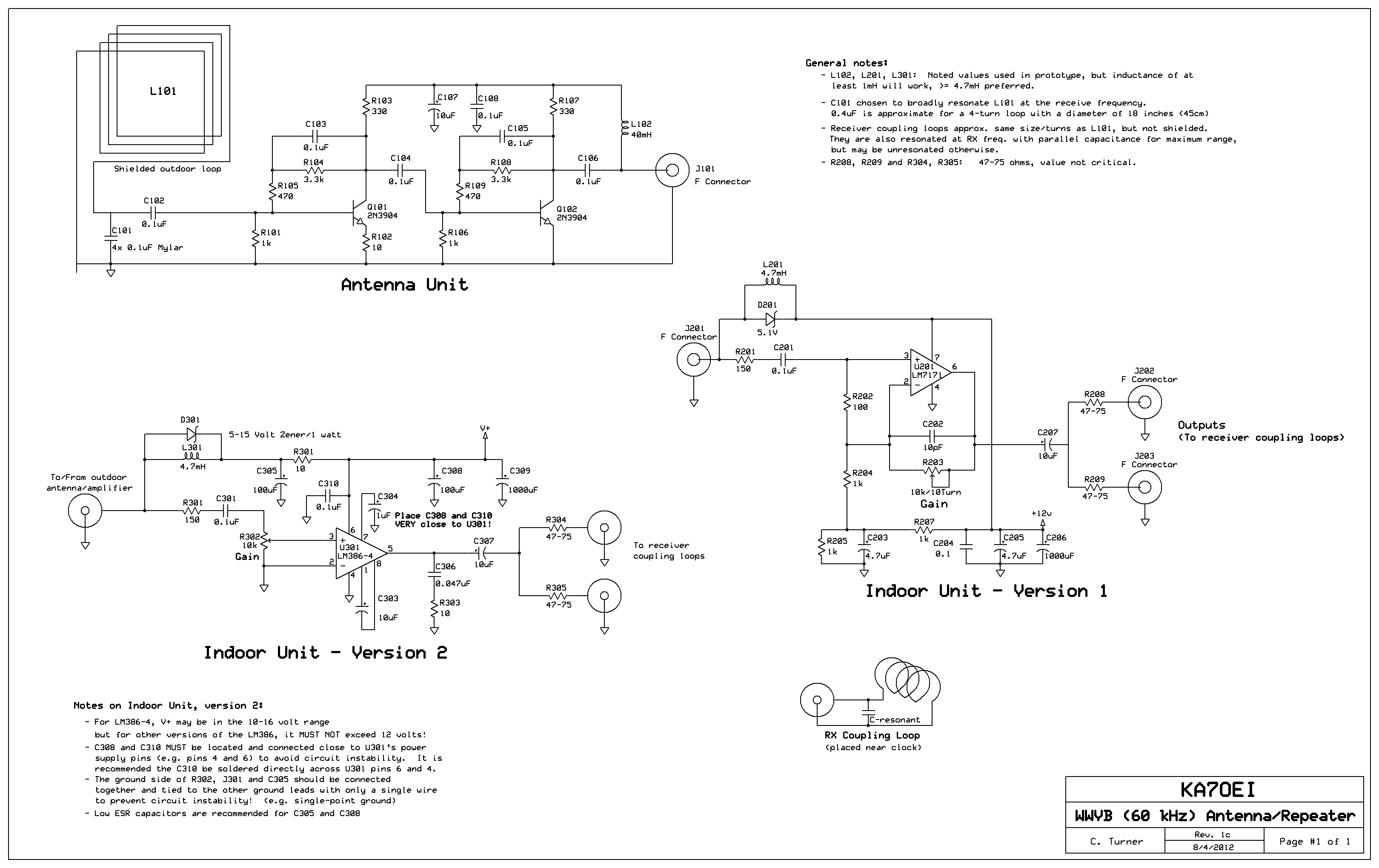
Inside the outdoor box where the loop is mounted, the amplifier circuitry is displayed. The four capacitors located at the lower-left corner of the perfboard are used to broadly resonate the receive loop. In the office building, which is...
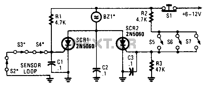
Two SCRs are utilized with two sensor loops. One loop employs series switches, while the other loop employs parallel switches. When a switch is actuated, the SCR is triggered. The alarm is designed to be a non-interrupting type. The circuit...
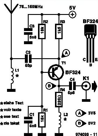
This inexpensive FM radio receiver antenna booster utilizes the BF324 TO92 style PNP transistor in a grounded-base configuration. The circuit can be employed as a... The FM radio receiver antenna booster circuit is designed to enhance the reception capabilities of...
One of the most challenging issues in an audio system is the presence of ground loops. These loops not only introduce hum but can also pick up interference from electric drills, computer hardware, and even AM radio stations. Eliminating...