
FM Radio Receiver Antenna Booster Circuit

The FM radio receiver antenna booster circuit is designed to enhance the reception capabilities of FM radio signals, particularly in areas with weak signal strength. The use of the BF324 TO92 style PNP transistor in a grounded-base configuration is crucial for optimizing the performance of the circuit. This configuration allows the transistor to operate with high input impedance while providing low output impedance, which is beneficial for signal amplification.
The circuit typically includes a few key components: the BF324 transistor, resistors for biasing, capacitors for coupling and decoupling, and an input/output connector for the antenna and radio respectively. The grounded-base configuration minimizes the impact of variations in the transistor's parameters, ensuring stable operation across a range of frequencies.
The input stage of the circuit connects the antenna to the base of the transistor through a coupling capacitor. This capacitor blocks any DC component from the antenna and allows only the AC signal (the FM radio signal) to pass through. The base resistor is employed to set the operating point of the transistor, ensuring that it remains in the active region for optimal amplification.
The output stage of the circuit connects the collector of the transistor to the radio receiver. An output capacitor is used to block any DC voltage from the collector while allowing the amplified AC signal to pass through to the radio. A load resistor may also be present to match the output impedance of the circuit with that of the radio receiver, maximizing power transfer.
In summary, this FM radio receiver antenna booster circuit effectively amplifies weak FM signals using a BF324 PNP transistor in a grounded-base configuration, making it a valuable addition for improving radio reception in challenging environments. Proper component selection and configuration are essential for achieving the desired performance characteristics.This inexpensive FM radio receiver antenna booster uses the BF324 TO92 style pnp transistor in a grounded-base configuration. The circuit may be used as a.. 🔗 External reference
Related Circuits
This report outlines the operation and adjustment of a Phase Locked Loop (PLL) hum cancellation circuit designed to reduce residual hum from amplifiers. This circuit is particularly useful for Directly Heated Triode (DHT) amplifiers with AC-operated filaments, where a...
Individuals seeking a distinctive gift for Christmas and New Year may find this project appealing. Certification of this project will undoubtedly create a preference for it. The project in question appears to be a creative endeavor aimed at providing a...
The schematic diagram presented below illustrates a simple FM receiver constructed using four transistors. The signal from the antenna passes through the trimmer capacitor C1 before reaching the input of the first stage, which operates as a super-regenerative detector...
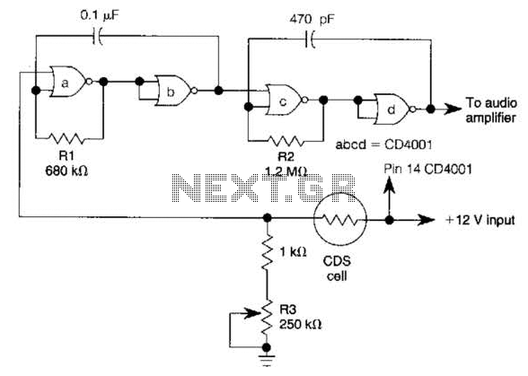
NOR gates A and B create a low-frequency oscillator that activates when the CDS cell, in dark conditions, presents a logic zero to one input of NOR gate A. This low-frequency oscillator, operating at 10 Hz, enables a high-frequency...
The 74AC240 stepper driver works by alternately enabling each half of the buffer. Only one half can be enabled at a time. Let’s assume that the top half of the driver is enabled. U1A & U1B along with R8,...
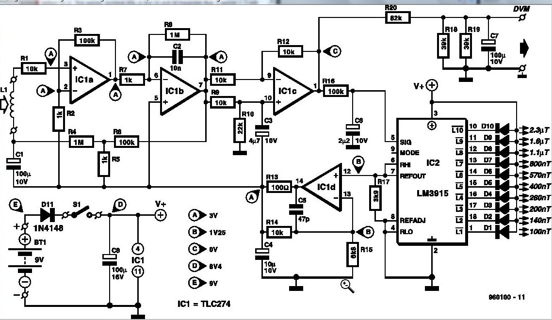
Some experts believe that static magnetic fields (SMFs) may affect the physical well-being of individuals. If one subscribes to this viewpoint, the magnetic-field meter described here will aid in locating sources of SMFs and assessing their strength. These results...