
R/C Thermal Peak Detection NiCd Charger

The charger circuit is designed to efficiently manage the charging of nickel-cadmium (NiCd) battery packs, specifically those consisting of 4 to 7 cells in series. This configuration allows for a flexible range of battery capacities, accommodating packs from 600mAh to 2Ah. The automatic initiation of the charging process upon connection of a battery pack enhances user convenience, as no manual intervention is required.
The core charging mechanism relies on a nearly constant current approach, which is adjustable to suit the specific requirements of the connected battery pack. This feature is critical in ensuring that the batteries are charged safely and effectively, preventing overcharging and potential damage. The termination of the charging process is intelligently managed by monitoring the temperature of the battery pack. As NiCd batteries reach full charge, they exhibit a slight increase in temperature; this characteristic is utilized to signal the charger to cease current flow, thereby safeguarding the battery's integrity.
An LED indicator is incorporated into the design to provide visual feedback regarding the charging status. When the charger is actively charging a battery pack, the LED illuminates, serving as an assurance to the user that the process is underway.
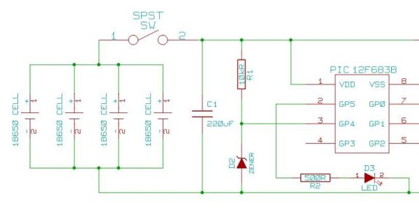
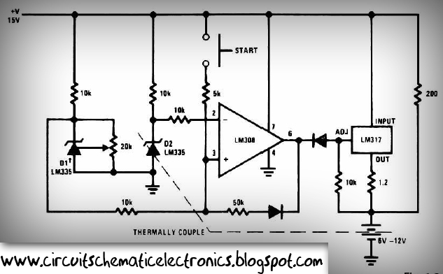
The operational backbone of the circuit is the comparator Z1A. This component plays a pivotal role in monitoring the voltage levels at its two inputs. The "+" input (pin 5) is connected to a reference voltage, while the "-" input (pin 6) receives the voltage from the battery pack. When the voltage at the "+" input exceeds that at the "-" input, Z1A outputs a high signal, indicating that charging should continue. Conversely, if the voltage at the "-" input rises sufficiently—typically due to the battery's temperature increase—the output of the comparator transitions to a low state, triggering the cessation of charging.
This simple yet effective design ensures that the charger operates within safe limits while providing the necessary functionality for charging NiCd packs, making it a reliable choice for users seeking an uncomplicated charging solution.The charger described in this article can charge packs of 4 to 7 cells with capacities ranging from 600mAh to 2Ah. The charger automatically begins charging when a pack is connected. It charges at a (nearly) constant current (adjustable), and terminates the charge when the pack begins to get warm (a NiCd pack begins to warm up when it has reached full charge).
An LED indicates that charging is in progress. The circuit for the charger (Figure 1) is simple. Z1A is a comparator which compares the voltage on its two inputs and produces a high output when the "+" input (pin 5) is higher than the "-" input (pin 6), and a low output otherwise. 🔗 External reference
Related Circuits
It's just a simple power supply with a 7805 regulator. The chip must be mounted on a large metal radiator because the current requested by the regulator is near 0.4 A. However, to lower the power, you can put...
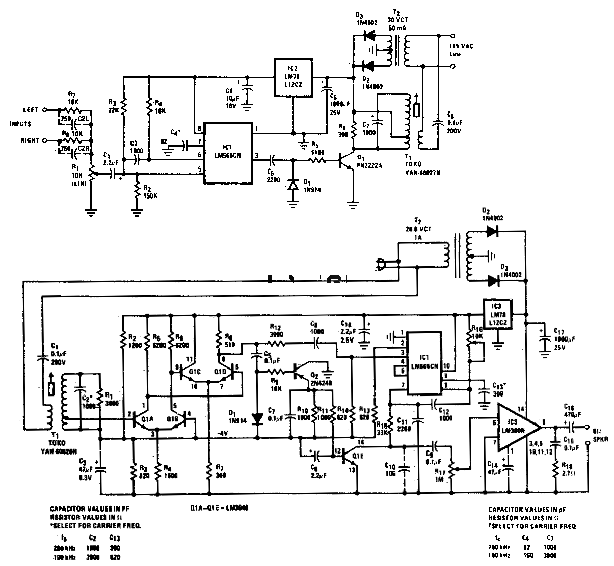
A high-quality, noise-free wireless FM transmitter and receiver operates over standard power lines. The complete system is designed for high-quality transmission of speech or music and can function from any AC outlet within a one-acre residential area. The frequency...
Heavy-duty portable charger for USB devices (phones, iPad, etc.). Have you ever needed to charge your phone on the go? Unable to find a wall socket to charge your iPod?.. The heavy-duty portable charger is designed to provide a reliable...
After one has built a QRP transmitter, it would be interesting to know the exact amount of output power. Without a power meter, the peak to peak voltage Vss is measured at a 50-ohm resistance (dummy load) with the...
This circuit is designed for rapid battery charging. It is recommended for those who require a faster charger. The charger operates at a low temperature of 5 degrees Celsius. The input voltage is 15 volts DC, while the output...
This battery charger circuit is regulated and adjustable, enabling it to charge most NiCAD batteries. It is suitable for single cells or multiple battery cells connected in series or parallel configurations. The maximum... This battery charger circuit is designed to...