
F007 stable sine wave oscillator circuit diagram

The stable sine wave oscillator circuit operates on the principle of negative feedback to regulate its output. The design typically consists of an amplifier stage where the gain is set to a level that allows for sustained oscillation. The circuit's stability is critical; thus, it is essential to maintain the loop gain within specific limits.
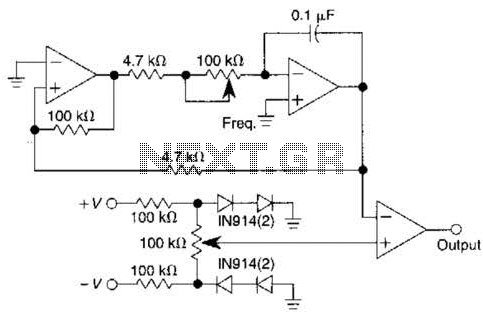
The two diodes in the circuit play a crucial role in the feedback mechanism. When the output voltage falls below a specific threshold, the reverse-biased diode effectively removes negative feedback, which allows the gain to increase and the output voltage to rise. This action continues until the output voltage exceeds the threshold, at which point the diode becomes forward-biased. This transition reduces the gain, leading to a decrease in output voltage, thereby creating a self-regulating oscillation cycle.
The potentiometer included in the circuit allows for fine-tuning of the output amplitude and distortion. By adjusting the resistance, the user can modify the feedback level, which directly impacts the output waveform's characteristics. This feature is particularly useful in applications requiring precise control over the output signal.
The frequency of oscillation is determined by the values of the resistor and capacitor in the circuit. The relationship is defined by the equation f0 = 1/(2πRC), where f0 represents the frequency of oscillation, R is the resistance, and C is the capacitance. By selecting appropriate values for R and C, the desired frequency can be achieved, making this circuit versatile for various applications in signal generation and waveform synthesis.
This stable sine wave oscillator circuit can be implemented in various electronic applications, such as audio signal generation, waveform shaping, and clock pulse generation. Its design ensures reliability and stability, making it suitable for both experimental and commercial use. As shown for the stable sine wave oscillator circuit. In order to obtain stable oscillation, the loop gain of claim 1. If the gain is too large, the waveform distortion; if the gain is too small, will appear to stop vibration. This circuit uses two diodes to stabilize oscillation. When the output voltage is too low, the diode is turned off, the negative feedback is cut off, the loop gain is increased, the output voltage is increased. When the output reaches a certain value, the diode is turned on, the loop gain is reduced. Output voltage decreases, and so forth, so that the output amplitude stability at a certain value. FIG potentiometer used to adjust the output amplitude and distortion. The oscillation frequency of the circuit is determined by the resistor R and the capacitor C, its size is:f0 1/2 RC.
Related Circuits
One of the simplest methods of metal detection is through a beat frequency oscillator. The circuit consists of two balanced oscillators: one provides a reference signal, while the other acts as the detector element. The frequency of the reference...
This circuit dials a stored DTMF tone sequence from an EPROM when a control line is taken to 0 V. IC1 is a Schmitt trigger oscillator, operating at approximately 2 Hz. It clocks a 4024 binary counter. The outputs...
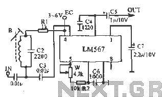
This figure illustrates the schematic of the LM567 SCA broadcast reception information machine. The LM567 serves as a narrow-band phase-locked loop designed primarily for SCA broadcast demodulation. The configuration includes a potentiometer (W) and capacitor (C6) that determine the...
This pulse generator utilizes a single integrated circuit (IC) and six passive components to achieve a frequency range of 400 to 4000 Hz, with an adjustable duty cycle ranging from 1% to 99%. The circuit employs a threshold detector...
The FM modulator circuit, which utilizes frequency modulation, is constructed using a Motorola MC1648P oscillator. Two varactors, specifically Motorola MV-209, are employed to modulate the frequency of the oscillator. A 5000-ohm potentiometer is incorporated to bias the varactors for...
A square wave oscillator utilizing the 555 integrated circuit (IC) can be configured to produce symmetric oscillation with a 50% duty cycle. Additional circuit configurations employ diodes to separate the charging and discharging paths. The 555 timer IC is a...