
Radio Glen Transmitter

Technical Specification: Modulator Unit
Power: 240V mains
Audio Input: Stereo standard line level 0dbm 775mVrms on XLR sockets balanced input.
Indicators: Mains neon, 5V rail LED, 22V rail LED, crystal oven heater LED
Controls: Mains on/off rotary switch
Frequency Ref: Ovened crystal driving PLL frequency divider
Output frequency: Supplied as 1602kHz +/- 2Hz for University Radio Glen. (now modified to 1287kHz)
RF output level: Approx 2Vpp with 80% modulated AM signal
Output connector: Female BNC
Case: Standard 19” rack mount ?U
Mod bandwidth: -3dB at 6kHz from carrier, -40dB at 9kHz as required by WT regs.
Modulation limiting: Will not exceed 100% modulation with transient +10dBm 1kHz tone burst.
Technical Specification: PA Unit
Power: 240V mains
Input: Variable 0.5 to 2Vpp with 80% modulated AM signal
Indicators: Mains neon, 30V rail LED, Unregulated supply LED.
Controls: Dual on/off for each section. Dual input attenuators for each section.
Output: 10W AM into 50 ohms from each section.
Input connectors: Female BNC
Output connectors: Female BNC
Input impedance: Approx 1kohm each section
Output Impedance: 50ohm
Output harmonics: 40dB down on the main carrier as required by WT regs.
The transmitter system integrates a modulator and power amplifier (PA) unit, designed for AM transmission. The modulator unit operates from a 240V mains supply, accepting balanced audio input from XLR sockets at standard line levels. It employs an ovened crystal to stabilize the output frequency, initially set to 1602kHz and currently modified to 1287kHz, with a permissible deviation of +/- 2Hz. The RF output level is approximately 2Vpp, modulated at 80%, and is connected via a female BNC connector.
The modulation bandwidth is specified with a -3dB point at 6kHz and -40dB at 9kHz in compliance with wireless telegraphy regulations. The modulation limiting is designed to prevent exceeding 100% modulation during transient conditions, ensuring signal integrity.
The PA unit also operates on a 240V mains supply, designed to amplify the modulated signal to 10W into a 50-ohm load. It features input and output connectors, both female BNC, and dual on/off controls for each section, along with variable input attenuators. The input impedance is approximately 1k ohm per section, ensuring compatibility with various audio sources.
The frequency synthesizer within the modulator utilizes a 74HC4060 integrated circuit to generate a 9kHz reference signal for the voltage-controlled oscillator (VCO), which is pivotal for maintaining the desired output frequency. The output from the VCO is processed through a series of dividers and phase comparators to ensure precise frequency control. The system includes careful filtering to minimize phase noise, with a dedicated 5V regulator for the VCO to stabilize its operation.
The modulation process is executed using the MC1496 modulator, which operates in a differential saturated mode to enhance performance without requiring complex balancing components. The RF output stage is designed to deliver a clean AM signal, with tuned transformers filtering out unwanted harmonics. The overall design emphasizes reliability and adherence to regulatory standards while allowing for flexibility in frequency adjustment as needed.
The system also incorporates a crystal oven heater controlled by an LM393 comparator, ensuring the crystal operates at optimal temperatures for frequency stability. This control circuit includes hysteresis to maintain stable operation, while supply line glitches are mitigated through careful circuit design. The integration of NE572 compandors for audio compression enhances the signal quality, allowing for effective dynamic range management in the transmitted audio.This document describes the transmitter system supplied to Radio Glen for testing as designed and constructed by Henry. The transmitter is supplied in prototype form and has the physical limitations of an instrument constructed using prototyping techniques.
The transmitter has been designed to conform to the Radio Authority and Wireless Telegraphy requirements but the user must realise that this transmitter has not passed formal type approval tests. The operating station licensee and the technical manager bear the responsibilty of ensuring that the transmitter is not used in such a way as to cause interference to other wireless services or as to cause danger due to electrical shock or fire.
Due to the increased power output capability of the transmitter it is especially essential that the signal distibution system is maintained in good condition and checked regularly. Technical Specification: Modulator Unit Power: 240V mains Audio Input: Stereo standard line level 0dbm 775mVrms on XLR sockets balanced input. Indicators: Mains neon, 5V rail LED, 22V rail LED, crystal oven heater LED Controls: Mains on/off rotary switch Frequency Ref: Ovened crystal driving PLL frequency divider Ouput frequency: Supplied as 1602kHz +/- 2Hz for University Radio Glen.
(now modified to 1287kHz) RF output level: Approx 2Vpp with 80% modulated AM signal Output connector: Female BNC Case: Standard 19” rack mount ?U Mod bandwidth: -3dB at 6kHz from carrier, -40dB at 9kHz as required by WT regs. Modulation limiting: Will not exceed 100% modulation with transient +10dBm 1kHz tone burst. 5. Technical Specification: PA Unit Power: 240V mains Input: Variable 0.5 to 2Vpp with 80% modulated AM signal Indicators: Mains neon, 30V rail LED, Unregulated supply LED.
Controls: Dual on/off for each section. Dual input attenuators for each section. Ouput: 10W AM into 50 ohms from each section. Input connectors: Female BNC Output connectors: Female BNC Input impedance: Approx 1kohm each section Ouput Impedance: 50ohm Output harmonics: 40dB down on the main carrier as required by WT regs This sheet shows the frequency synthesiser and modulator. The 74HC4060 uses a cheap 4.608MHz crystal to develop the 9kHz reference required for the VCO. The internationally agreed channel spacing in Europe on MW is 9kHz so all other frequencies are available by fairly simple circuit changes.
The exact frequency of the output should be adjusted with the 10pF trimmer only when the circuit is fully warmed up and the crystal oven is operating normally. It is sufficient to adjust this by measuring the final output of the system at 1602kHz. The signal should be 1602kHz +/- 2Hz, so a frequency counter with seven or more digits is needed. The 74HC4046 has a centre operating frequency of approximately 1602kHz and a range of about 200kHz above and below this.
Output from the VCO is divided by 178 in the 74HC4059 to form the comparison signal to feed into the phase comparator with the reference signal. If a frequency other than 1602kHz is required, this can be obtained by changing the setting of the divider.
If a large change of frequency is required (eg for use on 963 or 999kHz) the loop filter and VCO free running components will also have to be changed. The values for all the resistors and capacitors of the VCO and reference oscillator can be found in the National Semiconductor or Philips HCMOS databooks.
The only unusual component is the 100nF capacitor filtering pin 9 of the VCO. This reduces 9kHz phase noise on the output signal. (audible when tuned just off centre of the signal with an AM radio). The 10M resistor reduces phase noise also, though the mechanism by which this is happening is not fully understood. A better loop filter than the simple one used here is proposed for the next design iteration, using a 2 pole active filter rather than the 100nF capacitor, with the other filter components being similar.
Schmitt triggers buffer the signal output and form an inverse of it. The true and inverse 1602kHz square waves are fed into the carrier inputs of the MC1496 modulator. The use of the true and inverted signals operates the modulator in a differential saturated mode. (See the Motorola or National Semiconductor databooks) This avoids the need for special balancing components and a constant amplitude carrier signal source. The 1k pot on pins 2 and 3 on the modulator is the only gain control in the RF section. This sets the RF output level ultimately delivered to the PA via the coaxial cable. The tuned transformer acts as a filter removing the higher order harmonics from the signal. This should be peaked for maximum output. Unbalanced audio is fed into the modulator. As the desired output signal is AM, not SSB or DSB, exact balancing is not important. The amount of residual carrier fed through with no audio is set by the ratio of the two resistors on pins 1 and 4 of the modulator.
The stability of the modulator and these resistors is important as they effectively set the audio sensitivity of the modulator. Care must be taken to avoid noise and voltage dips on the 5V line as the VCO is sensitive to supply line changes.
To this end, a separate 5V regulator has been included for the VCO alone, run from the 22V regulated rail. The PSU is straightforward and is covered adequately in the National Semiconductor regulator databook.
The crystal oven heater control circuit uses an LM393 comparator and a Philips NTC thermistor. Points worth noting are the thermistor which is glued onto the top of the crystal with epoxy and the 120R heater resistors which surround the crystal on two sides and are also glued to it. The circuit has hysteresis provided by the comparator itself and the 2.2M feedback. This means that the BD139 operates in saturated mode except when switching, and the whole system is "stable", in so much as it is guaranteed to oscillate about the temperature set point reliably.
Supply line glitches are minimised by the 47uF capacitor on the base of the BD139 slowing down the transistor switching time. Even so, a separate supply line and ground return direct to the regulator must be used for the heater current so that the VCO is not disturbed when the heater switches on and off.
This is not shown schematically. Though not intended to be a deeply precision circuit, this should be sufficient to keep the crystal at an approximate elevated temperature of 30 or 40 degrees C, in order to ensure that the output is kept to +/-2Hz. The 10K pot on the inverting input sets the temperature which ought to be set with a therocouple or similar attached to the crystal.
In practice, I would set it such that the heater comes on with about a 10% duty cycle at room temperature. The RF output stage currently uses a Nat Semi LM6361 shown. The output biasing diodes are glued to the metal transistor cases. The 2.2pF feedback resistor rolls off the output at frequencies much above 2MHz. This driver can give the required 2Vpp into 50R even with the 47R series output resistor. This resistor ensures that the output impedance is close to 50R and should avoid problems even if the cable to the PA is badly terminated.
The 4.7K resistor on the RF line should not be any higher than this value or else the transformer on sheet MOD01-01.SCH exhibits too high a Q value and starts to filter out the AM sidebands. Each of the low, mid and high sections are taken to nearly identical compressor stages. The stages for the low and mid bands are shown on MOD01-04.SCH. These are based around the inexpensive Philips NE572 compandor. These devices have several advantages over similar devices such as the technically superior SSM2120 from Analog Devices.
1) They are a lot cheaper and more widely available. 2) They work from a single supply - the SSM2120 does not, without going to extreme lengths. 3) The NE572 has independent attack and decay capacitors. 4) The NE572 does not have the pathological high frequency input oscillation of the expensive Analogue Devices part. The compressors are wired according to the Philips databook, with the unity gain point being set at 0dB for this application.
This is more a matter of convenience for testing than function. The compressors are wired in such a way that they inherently produce 2:1 compression, ie a 2dB increase in the input will produce only a 1dB increase in the ouput. Producing ratios other than 2:1 1:2 or infinite (limiting/AGC behaviour) with the NE572 is difficult, and so our compression ratio is conveniently chosen for us.
The attack capacitors are the smallest that can be used without getting a significant loss of level detection performance. As there are higher audio frequencies involved, the attack capacitors on the higher frequency sections have lower values.
🔗 External reference
Related Circuits
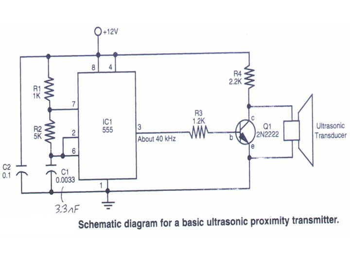
This section provides step-by-step instructions along with images for constructing an Ultrasonic Proximity Transmitter. Due to the simplicity of the circuit, only a schematic for the sensor is presented here. The objective of this tutorial is to assist others...
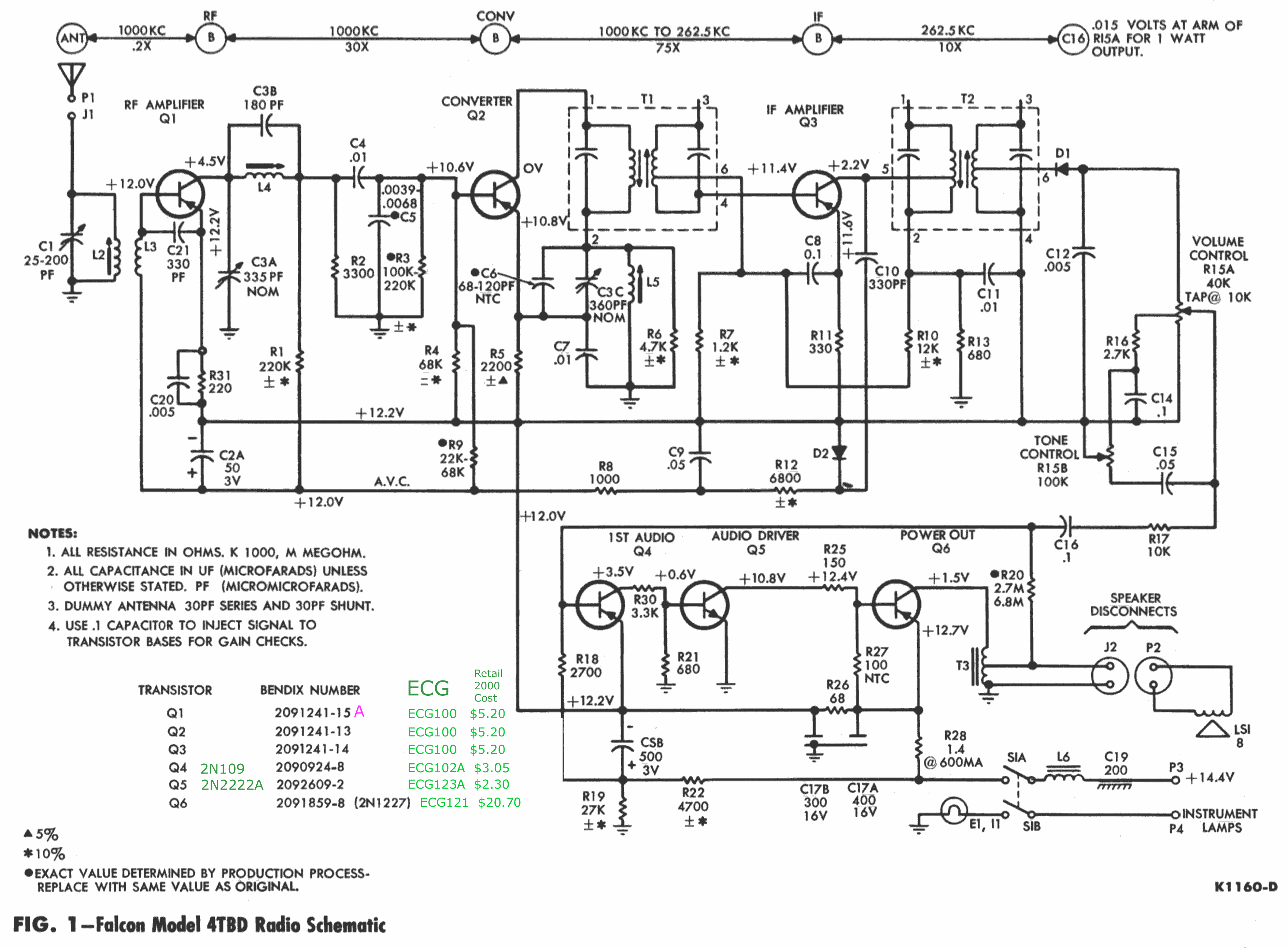
The chassis externally resembles the 22BD model, with the exception that the 22BD features a jack for speaker connections—two female sockets—located on the right (antenna) side. In contrast, the 3BTD model has a 3-inch harness (black and green wires)...
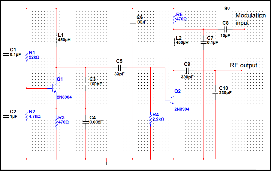
This circuit is a simple two-transistor (2N2222) mini FM transmitter. No authorization is required for this transmitter according to FCC regulations regarding wireless microphones. When powered by a 9-volt battery and equipped with an antenna no longer than 12...
The transmitter operating at 2 meters (144 MHz) was primarily designed for use by radio amateurs as a radio beacon. It generates a high-quality signal suitable for this purpose. The 2-meter transmitter circuit typically includes several key components to ensure...
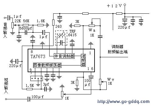
The circuit design philosophy allows for debugging without any RF instruments. Although its performance may not match that of professional equipment, it should be adequate for hobbyists, with audio-visual transmission effects comparable to general-purpose machines. The transmitter consists of...
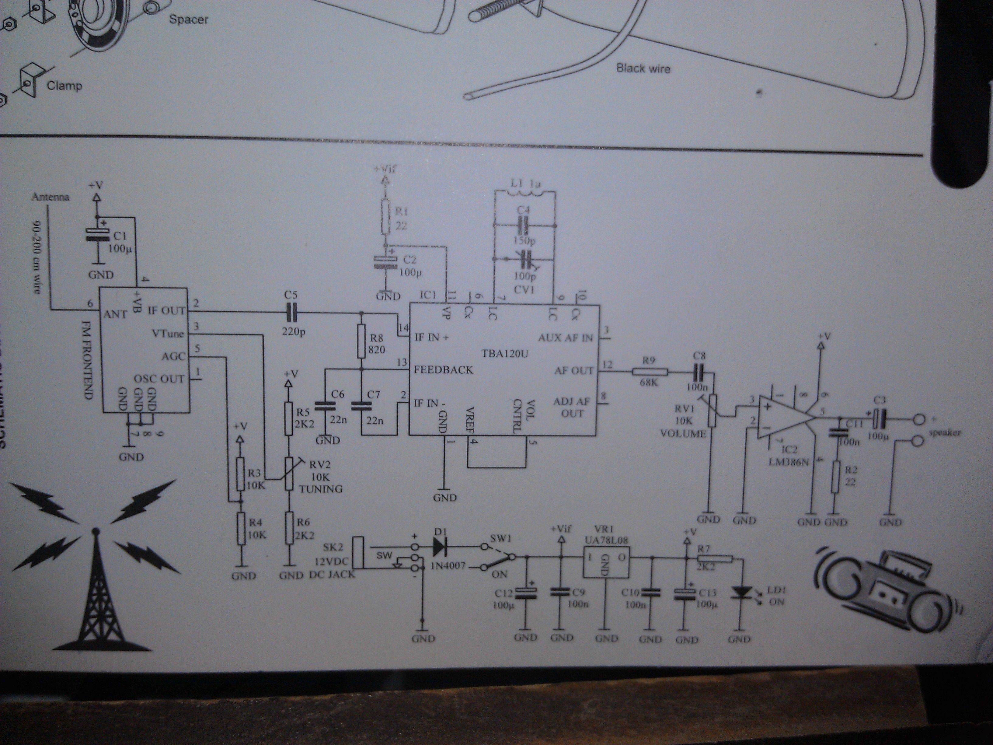
An FM Radio kit manufactured by Velleman-Kit and sold by Radioshack was recently assembled. The assembly process took approximately two hours, primarily due to distractions. The instructions provided are generally easy to follow, but they lack explicit details regarding...