
Rain alarm

The circuit design consists of two primary oscillators, each employing NAND gates to create square wave outputs. The first oscillator, comprising IC1a and IC1b, operates by utilizing one gate as an inverter while the other gate serves as a control mechanism. The control input of the second gate is critical for determining the operational state of the oscillator. When the control input is low, the oscillator is disabled, preventing any oscillation from occurring.
The sensitivity control is implemented through a high-value resistor (R1), which connects the control input to ground. This configuration ensures that the oscillator remains inactive until a certain threshold is met, specifically when moisture is detected on the sensor track. The presence of moisture effectively pulls the control input high, allowing the oscillator to generate a square wave output with a frequency of approximately 10 Hz.
This 10 Hz square wave output is then used to gate the second oscillator, which consists of IC1c and IC1d. This second oscillator operates at a higher frequency of 500 Hz, providing a rapid pulsing signal that is suitable for driving a loudspeaker. The output from the 500 Hz oscillator is routed through resistor R6, which serves to limit the current to the loudspeaker and protect the circuit from potential damage.
To amplify the signal for the loudspeaker, a Darlington pair configuration is employed using transistors Q1 and Q2. This arrangement provides high current gain, allowing the circuit to drive the loudspeaker effectively. Resistor R7 is included in the circuit to further ensure the stability and proper operation of the transistors within the Darlington pair. Overall, this circuit effectively combines sensor input with oscillator functionality to produce an audible signal, demonstrating a practical application of digital logic in electronic design.The circuit uses four NAND gates of a 4011 package. In each oscillator, while one gate is configured as a straightforward inverter, the other has one input that can act as a control input. Oscillator action is inhibited if this input is held low. The first oscillator (ICla and IClb) has this input tied low via a high value resistor (Rl) that acts as a sensitivity control.
Thus this oscillator will be disableduntil the control input is taken high. Any moisture bridging the sensor track will so enable the output which is a square wave at about 10 Hz This in turn will gate on and off the 500 Hz oscillator formed by IClc and ICld. This latter oscillator drives the loudspeaker via R6, the Darlington pair formed by Q1 and Q2, and resistor R7.
Related Circuits
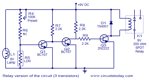
This document describes a simple fire alarm circuit utilizing a Light Dependent Resistor (LDR) and lamp combination for fire detection. The alarm activates by detecting smoke generated during a fire. When smoke is present, the circuit triggers an audible...
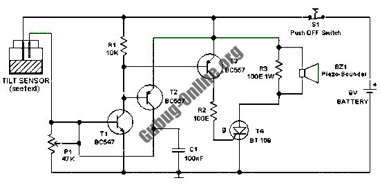
This design features a simple circuit for a tilt sensor alarm that can be constructed using readily available and inexpensive components. The circuit is based entirely on transistor technology. The homemade tilt sensor for this circuit utilizes a standard...
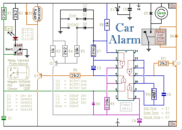
This circuit includes automatic exit and entry delays, an optional instant alarm zone, an optional intermittent siren output, and an automatic reset feature. By incorporating external relays, it is possible to immobilize the vehicle and activate the lights. For...

This is a simple single-zone burglar alarm circuit. Its features include automatic exit and entry delays. It is designed to be used with commonly available normally-closed input devices such as magnetic reed contacts, micro switches, foil tape, and passive...
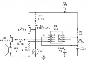
The following circuit illustrates a Sun Up Alarm Light Alarm Circuit Diagram. This circuit is based on the 555 Integrated Circuit (IC). Features include simplicity and cost-effectiveness. The Sun Up Alarm Light Alarm Circuit employs the 555 timer IC in...
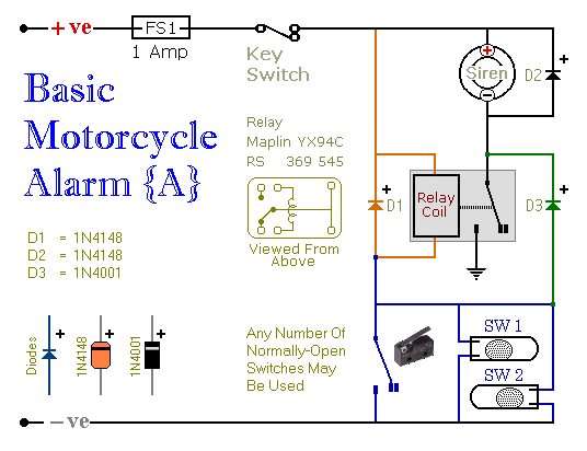
These are two easy to build relay-based alarms. You can use them to protect your motorcycle but they have many more applications. If you use relays with 6-volt coils, they'll protect your "Classic Bike". Both alarms are very small....