
(Sun Up Alarm) Light AlarmCircuit Based On The 555 IC
 Light AlarmCircuit Based On The 555 IC")
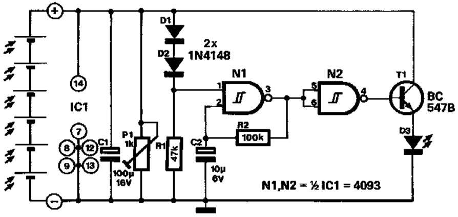
The Sun Up Alarm Light Alarm Circuit employs the 555 timer IC in an astable configuration to create a light-sensitive alarm system. The primary function of this circuit is to activate an alarm or light when ambient light levels drop below a certain threshold, signaling the onset of dawn or a specific time in the morning.
The circuit typically consists of a few key components: a 555 timer IC, a photoresistor (LDR), resistors, a capacitor, and an output device such as a buzzer or LED. The photoresistor is used to detect light levels; as the light diminishes, the resistance of the LDR increases, which alters the voltage at the threshold pin of the 555 timer.
In the astable mode, the 555 timer continuously switches between its high and low states, producing a square wave output. However, when the light levels fall below the predetermined point, the configuration changes, triggering the output device. The resistors and capacitor are chosen to set the timing characteristics of the circuit, allowing for customization of the sensitivity and response time of the alarm.
The simplicity of the design makes it an accessible project for beginners in electronics, while its low cost ensures it can be implemented in various applications, such as automated lighting systems or wake-up alarms. Overall, this circuit exemplifies an effective use of the 555 timer IC in creating a functional and practical light alarm system.The following circuit shows about (Sun Up Alarm) Light Alarm Circuit Diagram. This circuit based on the 555 IC Features: Simple circuit, cheap .. 🔗 External reference
Related Circuits

The circuit is designed to illuminate the third brake light (via SCR1 and SCR2) only when both the left and right brake lights are activated. The circuit operates on 12-V negative-ground systems. When the brake pedal is depressed, 12...
This circuit provides a visual 9 second delay using a 7 segment digital readout LED. When the switch is closed, the CD4010 up/down counter is preset to 9 and the 555 timer is disabled with the output held high....
The SN75604, which features input control logic and requires only a single supply rail, can be utilized in light activation sensors and alarm drivers. The device's Vqq and enable inputs are connected to a voltage lead from the light...
A novel application of solar cells simplifies the process of positioning a car in a garage, offering an improvement over traditional methods such as using old tires, mirrors, or chalk marks. The six solar cells depicted in Figure 1...

The days of arriving home at night and entering into darkness are finally over. This is a highly practical device, and it has been designed as a module. This device is intended to provide illumination upon entering a dark space,...

This circuit is designed for sound detection and generates an output signal when sound is detected. This output can trigger another circuit that activates an alarm, making it suitable for security applications. The circuit employs a condenser microphone to...