
Rain Detector Circuit Using NE555

The rain detector circuit based on the 555 timer IC is a practical application of basic electronic principles. The astable multivibrator configuration allows the circuit to continuously oscillate between high and low states, generating a square wave output at a frequency of 1 kHz. This oscillation can be used to trigger various actions, such as activating an alarm or turning on a light when rain is detected.
The circuit typically consists of the 555 timer IC, a few resistors, capacitors, and a water sensor. The water sensor is often made from conductive materials that allow for the detection of water by completing an electrical circuit when moisture is present. When water bridges the gap between the sensor's conductive elements, it changes the state of the 555 timer, thereby altering the output signal.
Powering the circuit with a voltage source of 5 to 15 VDC ensures compatibility with a wide range of applications, from small DIY projects to larger installations in vehicles or outdoor equipment. The design can be implemented on a printed circuit board (PCB) for durability and reliability, or can be constructed using simple materials such as foil on an insulated substrate for a more straightforward, cost-effective solution.
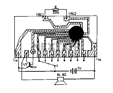
In summary, this rain detector circuit is an excellent example of how simple electronic components can be integrated to create a functional device that serves a practical purpose, such as protecting equipment from water damage. The ability to customize the design and easily implement it in various settings makes it a valuable project for electronics enthusiasts and professionals alike.Welcome to the weblog where we discuss about electronic circuits schematics, PCB design, diy kits and electronic projects diagrams. Rain detector using In principle it is an astable multivibrator 555, which is prepared by IC555 with a sensor attached that can detect water.
Astable multivibrator with the 555 is in the audio frequency with a freque ncy of 1 KHz. The use of rain detector circuit can be disupplay 555 with voltage source that is free enough as 5 to 15 VDC. In the application of rain detector circuit The use of this object 555 can be mounted engine, car and others who want to protect from rain.
Water sensor used in the rain detector circuit 555 Using this you can do yourself a PCB Degan make the path as shown in the image above or, as described from the image above is the use foil glued to a board or boards that are plastic insulation. The important principle of this sensor is to conduct electrical current very well when the surface is exposed to water even a little.
🔗 External reference
Related Circuits
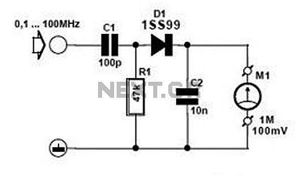
Comprehensive information about RF Probe Circuits is available. Users can learn about and download RF Probe Circuit designs online. RF Probe Circuits are essential tools for testing and analyzing radio frequency signals in various applications, including telecommunications, broadcasting, and electronic...
The need for a device that can detect and extinguish a fire on its own is long past due. Many house fires originate when someone is either sleeping or not home. With the invention of such a device, people...
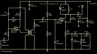
The TV transmitter described utilizes UK standard 1 FM modulation for sound and PAL modulation for video. The audio signal to be modulated is first amplified using transistor Q1 and its associated components. Transistor Q2 serves dual functions: generating...
This controller consists of three pairs of LED sensors arranged in a 3G-bridge configuration. The driver is capable of operating three actuators, with the motors connected in a Delta configuration. The apexes of the delta are linked to the...
The search loop can be constructed in various ways; however, the method presented here should provide a solid foundation. Refer to Fig. 2 as a guide for assembling the loop. The loop should be made from non-metallic and moisture-resistant...
Constantly changing light and sound analog controller circuit 05 The circuit described is an analog controller designed to modulate light and sound in a dynamic manner. This type of circuit typically employs a combination of resistors, capacitors, and operational amplifiers...