
rf probe circuit

RF Probe Circuits are essential tools for testing and analyzing radio frequency signals in various applications, including telecommunications, broadcasting, and electronic testing. These circuits allow engineers and technicians to measure the strength and quality of RF signals, making them invaluable for troubleshooting and development purposes.
Typically, an RF probe circuit consists of a few key components: an antenna or coupling device for signal reception, an amplifier to boost the signal strength, and a detection circuit to convert the RF signal into a readable format. The design may also include filters to eliminate unwanted frequencies and improve measurement accuracy.
The antenna can be a simple wire or a more sophisticated design depending on the frequency range of interest. The amplifier is usually a low-noise amplifier (LNA) to ensure that the signal integrity is maintained during processing. The detection circuit may employ a diode or a specialized RF detector IC to convert the RF signal into a DC voltage that can be easily measured on a multimeter or oscilloscope.
When designing an RF probe circuit, considerations such as impedance matching, bandwidth, and noise performance are critical for achieving accurate measurements. Proper layout and grounding techniques are also essential to minimize interference and ensure reliable operation.
Users can find numerous resources online, including schematics, component lists, and assembly instructions, to build their own RF Probe Circuits. These resources often include detailed explanations of each component's role and the overall function of the circuit, providing a comprehensive understanding of RF measurement techniques.Good information about RF Probe Circuit. You can learn and download RF Probe Circuit online.. 🔗 External reference
Related Circuits
This article discusses a fully automatic 6V 4.5AH battery charger circuit that utilizes the LM317T integrated circuit along with a few additional components. The circuit is designed to charge a 6V lead-acid battery. The circuit utilizes the LM317T voltage regulator,...
The series of decibel meters functions to determine the signal strength level delivered to the speakers in an audio system. This decibel meter circuit is commonly referred to as VU meters in high-fidelity audio systems. The series of decibel...
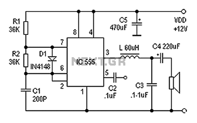
Also known as a digital amplifier, the Class-D amplifier is characterized by its compact size and high efficiency. This circuit utilizes a 555 timer IC to create a Class D amplifier. The 555 timer operates as a controllable multivibrator,...
A meter is a device designed to accurately detect and display an electrical quantity in a form that is readable by humans. This "readable form" is typically visual, such as the motion of a pointer on a scale, a...
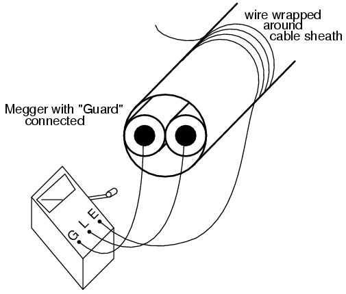
Working on live telephone circuits can be a problem. You just can't connect a normal scope probe to the circuit while it is tied to the phone line. Neither side of a phone line is ground. When a phone...
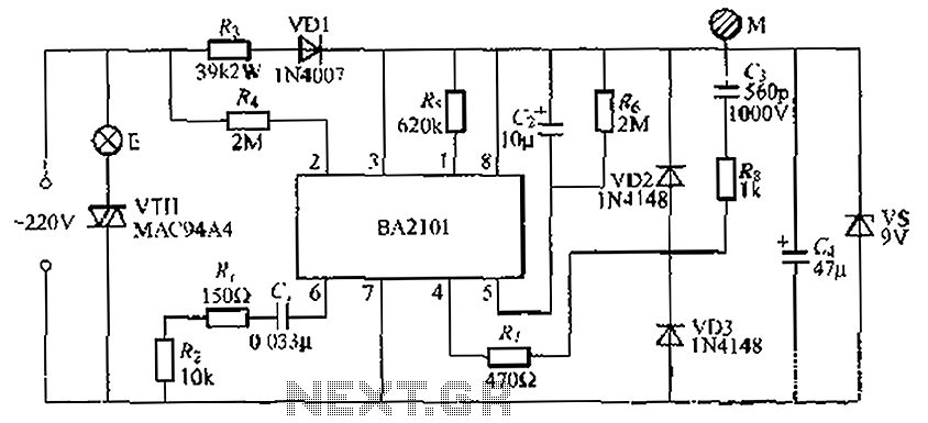
The BA2101 is a dimming controller utilizing an ASIC to create a barrel of light touch stepping. It is a non-constant lamp suitable for heir light. Each touch on the electrode sheet M can adjust the lamp brightness through...