
Ramp Generator

The described circuit is a voltage ramp generator that operates within a specified frequency range of 0.4 Hz to 100 kHz. It produces a linear voltage output that swings from 0 to 10 volts, making it suitable for applications requiring precise voltage control over a wide range of frequencies.
The core component of this circuit is an operational amplifier (IC1), which is configured to produce a ramp waveform. The ramp's positive slope is generated by the negative current flowing through the resistor Rl. This current is crucial as it dictates the rate of change of the output voltage. As the negative current charges the capacitor associated with the operational amplifier, the output voltage increases linearly toward the positive supply rail of +15 volts.
To achieve the desired frequency response, the values of the resistor Rl and capacitor must be carefully selected. The time constant of the RC network formed by Rl and the capacitor determines the slope of the ramp and, consequently, the frequency of the output waveform. The output can be fine-tuned by adjusting these component values, allowing for flexibility in applications.
The compact design of this circuit makes it ideal for integration into larger systems where space is a constraint. Additionally, the simplicity of the design allows for easy troubleshooting and modifications, enhancing its utility in various electronic applications.
In summary, this circuit serves as an efficient voltage ramp generator, leveraging the properties of an operational amplifier and passive components to deliver a linear output voltage across a wide frequency range while maintaining a small footprint. Providing a 0-to 10-V excursion from 0.4 Hz to 100 kHz, this circuit offers both simplicity and small size. The negative cur rent through Rl produces the ramp"s positive slope and causes the output of IC1 to increase linearly toward the + 15-V rail.
Related Circuits
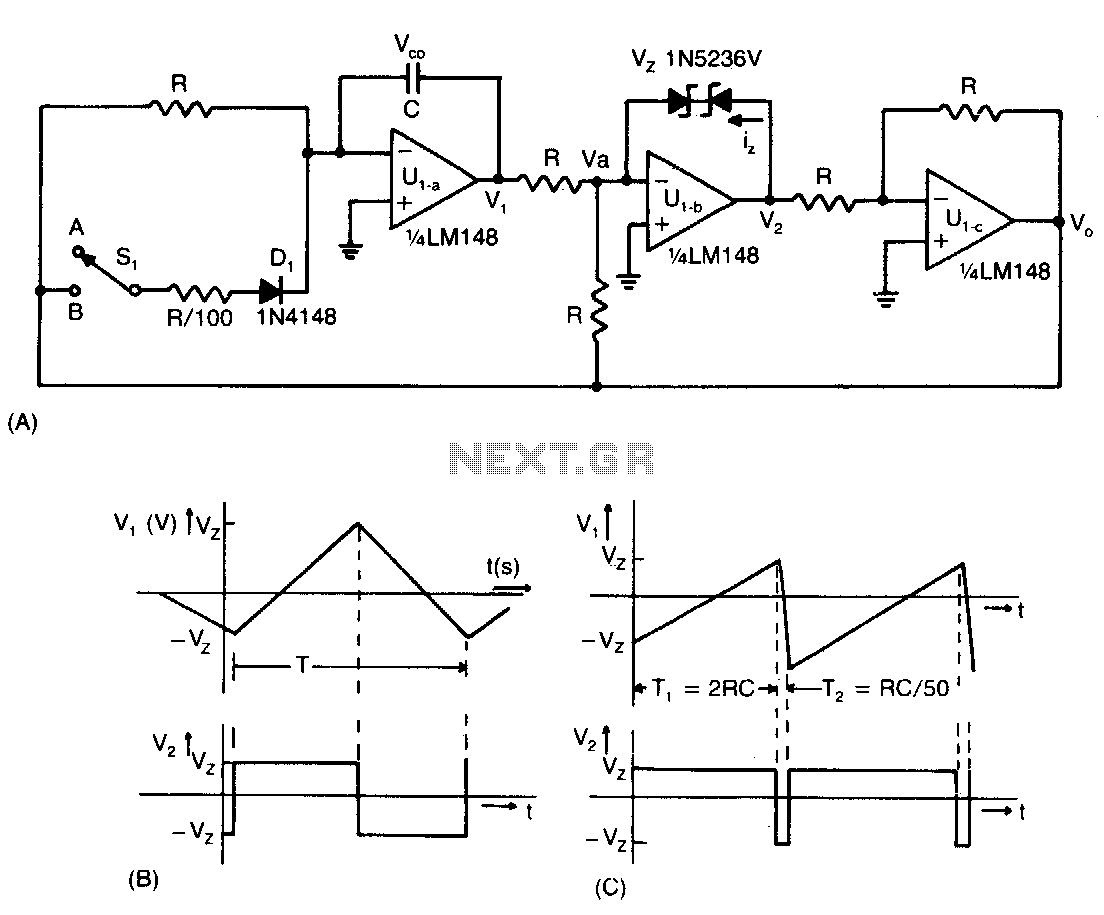
This low-cost operational amplifier circuit (A) generates four different functions with adjustable periods. For the components shown here, the period of the output waveforms is given by T = 4RC and T = 2RC. When switch SI is in...
The telephone ring generator described generates the necessary aerial voltage using a simple switched-mode power supply (SMPS). It incorporates a CMOS Schmitt Trigger-based oscillator, a 10 mH inductor, a high-voltage switching transistor (such as the TIP47 or another high-voltage,...
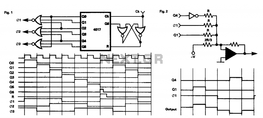
This circuit provides a three-phase square-wave output suitable for a variable speed motor drive. The operation is simple, as the 4017 counter is synchronously reset after six clock pulses. The outputs are combined to produce the necessary waveforms. It...
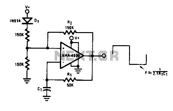
This self-starting fixed frequency oscillator circuit provides excellent frequency stability. R1 and C1 form the frequency-determining network, while R2 supplies regenerative feedback. Diode D1 improves stability by compensating for the difference between Voh and Vsupply. In applications requiring a...
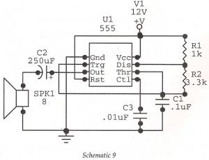
This circuit features an astable oscillator constructed around a 555 timer, generating an alarm tone of 1.8 kHz, which directly drives a speaker. It serves as a fundamental alarm circuit that can be utilized in various projects. Although the...
This circuit generates a stable 1 kHz sine wave using the inverted Wien bridge configuration. The inverted Wien bridge oscillator is a type of electronic oscillator that produces sine waves with high stability and low distortion. It operates on the...