
1khz sinewave generator

The inverted Wien bridge oscillator is a type of electronic oscillator that produces sine waves with high stability and low distortion. It operates on the principle of positive and negative feedback, utilizing an RC network to determine the frequency of oscillation. The circuit typically consists of operational amplifiers, resistors, and capacitors arranged to create a feedback loop that sustains oscillation.
In the inverted Wien bridge configuration, two resistors and two capacitors form the frequency-determining network. The resistors are connected in series, while the capacitors are in parallel, which allows for precise tuning of the frequency. The output frequency can be calculated using the formula:
\[ f = \frac{1}{2\pi R_1 R_2 C_1 C_2} \]
where \( R_1 \) and \( R_2 \) are the resistances, and \( C_1 \) and \( C_2 \) are the capacitances in the circuit. For a frequency of 1 kHz, appropriate values for the resistors and capacitors must be selected to meet this requirement.
The operational amplifier serves as the active element in the circuit, providing the necessary gain to sustain oscillation. The gain of the op-amp must be carefully set to ensure that it compensates for losses in the circuit while maintaining stability. A common approach to achieve this is by using a variable resistor in the feedback loop, which allows for automatic gain adjustment as the amplitude of the oscillation changes.
In practical applications, the output of the circuit can be connected to various loads, such as audio devices or signal processing equipment. The sine wave generated by the circuit is typically clean and free from harmonics, making it suitable for testing and calibration purposes in electronic systems. Proper power supply decoupling and layout considerations should be taken into account to minimize noise and interference in the output signal.This circuit generates a good 1KHz sinewave using the inverted Wien bridge configuration.. 🔗 External reference
Related Circuits
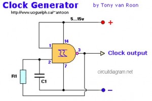
The following diagram represents a Clock Generator circuit that is constructed using NAND Gate logic integrated circuits (ICs). The circuit can utilize either IC 7400 or IC 4011. The 7400 is a TTL (Transistor-Transistor Logic) type, whereas the 4011...
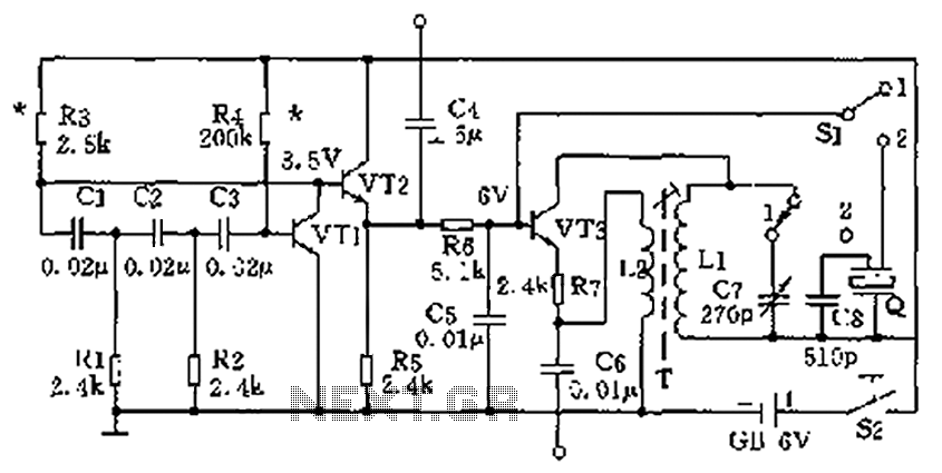
The high-frequency signal generator is designed to produce a low frequency of 1 kHz, an intermediate frequency (IF) signal of 465 kHz, and high frequencies ranging from 525 kHz to 1605 kHz. This device is particularly useful for radio...
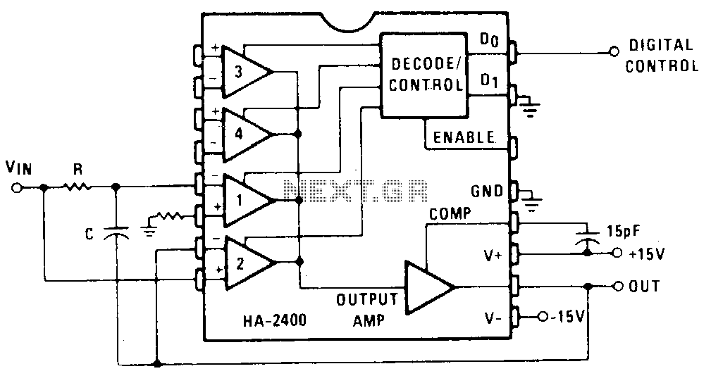
Channel 1 is configured as a conventional integrator, while Channel 2 is set up as a voltage follower. When Channel 2 is activated, the output will track the voltage of VJN, and capacitor C will discharge to maintain 0...
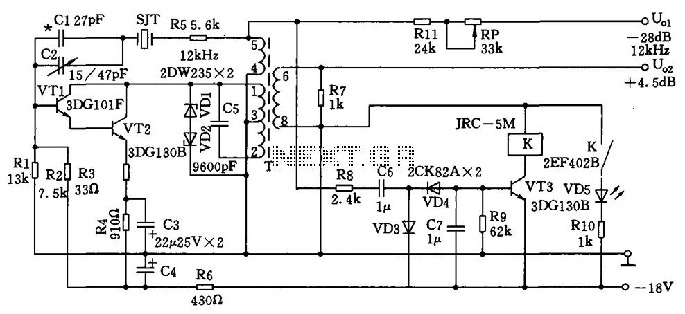
The circuit depicted is a 12 kHz intermediate frequency oscillator designed for an alarm system. It employs a variable feedback oscillation circuit where the oscillation frequency is primarily determined by a quartz crystal. Capacitors C1 and C2 are used...
Unique applications of the 567 tone/frequency decoder IC include its use as a pulse generator with a 25% duty cycle. This signal generator produces... The 567 tone/frequency decoder IC is a versatile component widely used in various electronic applications, particularly...
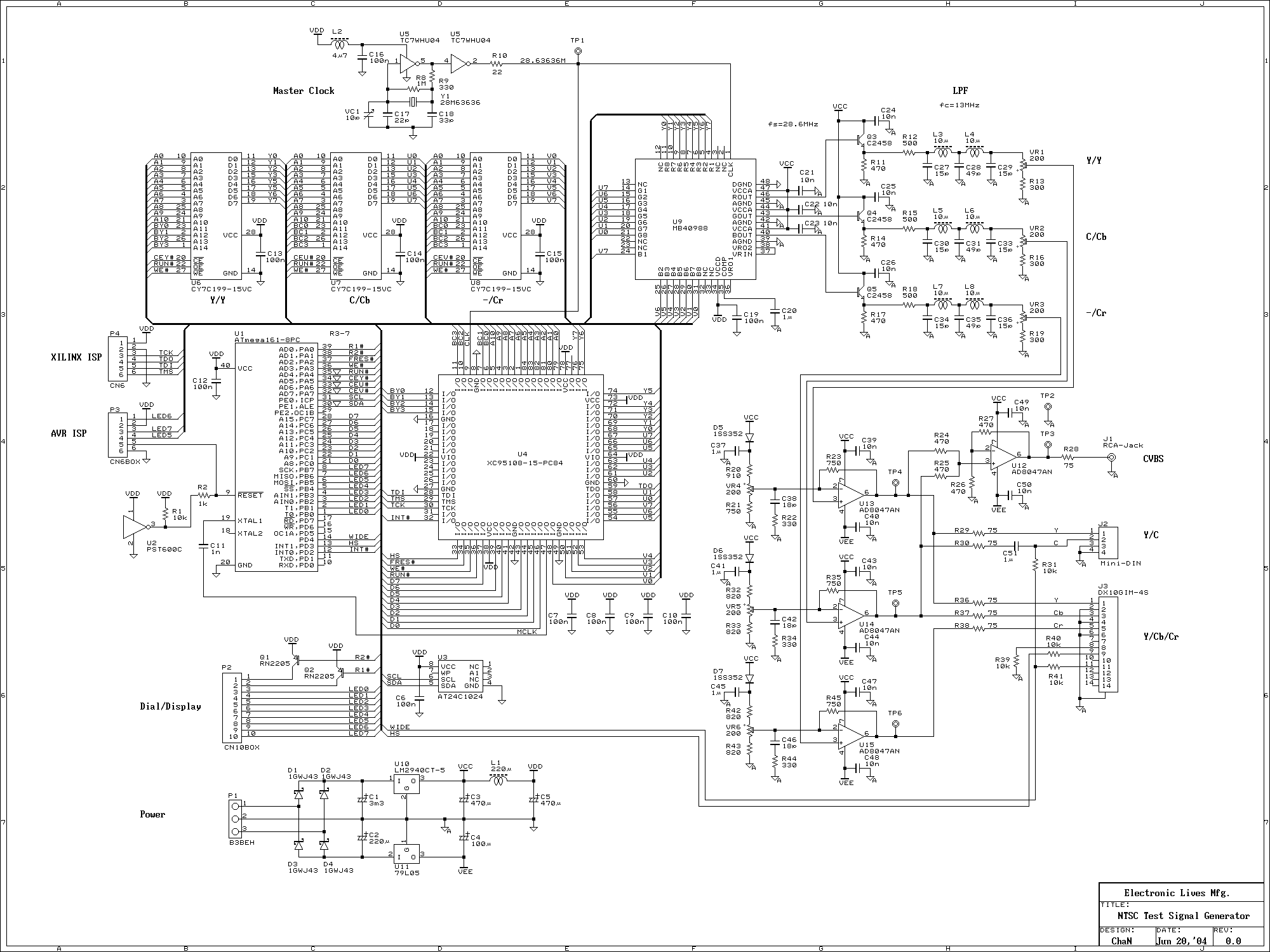
This signal generator uses a three channel DAC to generate Composite video signal (CVBS) and S video signal (Y/C separated) at the same time, left one channel is not used in NTSC format. It is assigned for one of...