
RC CONTROLLED DIGITAL CAMERA

The project involves integrating a digital camera into a lightweight electric radio-controlled (RC) aircraft, specifically a park flyer model. The design must ensure that the total weight of the aircraft, which ranges from 400 to 550 grams, remains within acceptable limits for stable flight performance. Key considerations include the selection of components that minimize weight while maintaining functionality.
The circuit schematic for this project would typically include the following key elements:
1. **Power Supply**: A lightweight lithium polymer (LiPo) battery is recommended, as it offers a high energy-to-weight ratio. The voltage rating should match the operational requirements of both the RC airplane's electronic speed controller (ESC) and the digital camera.
2. **Electronic Speed Controller (ESC)**: This component regulates the speed of the brushless motor and is connected to the battery and motor. It should be chosen based on the motor specifications to ensure optimal performance.
3. **Motor**: A brushless motor suitable for park flyers should be selected to provide sufficient thrust while keeping weight low. The motor's specifications must align with the battery and ESC to ensure compatibility.
4. **Digital Camera**: A lightweight, compact digital camera capable of capturing images or video is essential. The camera should be mounted securely within the fuselage of the RC airplane to avoid aerodynamic drag and ensure stability during flight.
5. **Receiver and Transmitter**: A 2.4 GHz RC receiver is necessary for controlling the aircraft. It should be connected to a compatible transmitter that allows for real-time control of flight maneuvers.
6. **Servos**: Depending on the design of the airplane, servos may be required for controlling the ailerons, elevator, and rudder. These should be lightweight and capable of providing adequate torque for effective control surfaces.
7. **Mounting and Integration**: The digital camera must be mounted in a way that minimizes vibration and movement, which could affect image quality. Additionally, careful routing of wires and components is essential to maintain the aircraft's center of gravity and balance.
8. **Weight Distribution**: It is crucial to ensure that the added weight of the camera does not adversely affect the aircraft's flight characteristics. Adjustments to battery placement or wing configuration may be necessary to achieve optimal balance.
Overall, this project requires careful planning and consideration of component selection to ensure that the integrated digital camera does not compromise the flight performance of the RC airplane.The aim of this project was to get a digital camera into a small electric radio controlled (RC) aeroplane and still have it fly. The aeroplane shown, a park flyer, weighs between 400 and 550 grams depending on the size of battery and wing configeration that I use.
🔗 External reference
Related Circuits
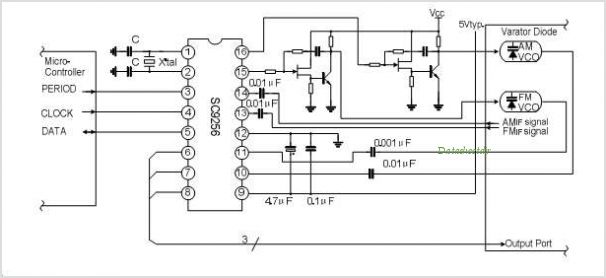
The SC9270C/SC9270D is a comprehensive DTMF receiver that integrates both bandsplit filtering and digital decoding functions. The filter section utilizes switched capacitor techniques to achieve high- and low-group filtering along with dial-tone rejection. The decoder employs digital counting techniques...
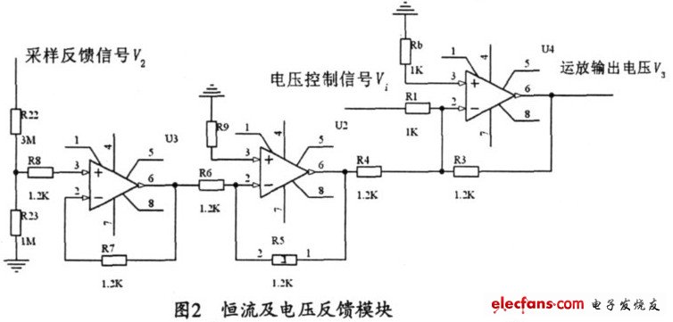
The output current range of the parameter current regulator is limited, and its precision is not high. Connecting the feedback adjustment type output current of the current-stabilized power source in series results in lower efficiency. The steady current source...
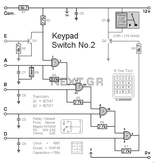
The Keypad Controlled Switch No2 Circuit operates with a 12-volt supply but is compatible with voltages ranging from 5 to 15 volts. The only requirement is to select a relay that matches the desired supply voltage. The Keypad Controlled Switch...
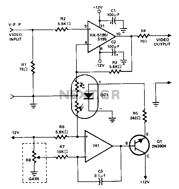
This amplifier utilizes a cascaded operational amplifier (op amp) integrator and a transistor buffer, Q1, to drive the gain control element. With a minor modification, the HA-5190/5195 stage is configured as a conventional non-inverting op amp and includes input...
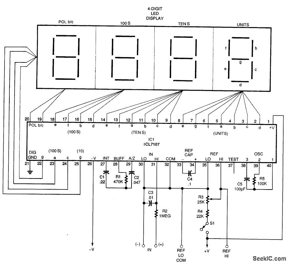
A basic digital voltmeter circuit utilizing the Harris Semiconductor ICL7107 is presented. It operates within a 2-V range. Calibration involves applying a known voltage of 1.2 V to the input and adjusting resistor R3 to achieve an accurate reading...
The output voltage of a thermocouple is converted into a frequency that is measured by a digital frequency meter. The output signal from the thermocouple is proportional to the temperature difference between the hot junction and a reference thermostat...