
Reading an SD card with an ATMEGA168

The described circuit utilizes the ATMEGA168 microcontroller, which operates effectively at 3.3V, facilitating direct interfacing with an SD card without the need for additional voltage regulation. This design choice simplifies the overall circuit by reducing component count and potential points of failure. The SPI interface is crucial for achieving high-speed communication between the microcontroller and the SD card, allowing for efficient data transfer rates suitable for applications requiring rapid access to stored data.
The initialization function, spi_init(), sets the necessary data direction registers for the MOSI (Master Out Slave In) and SCK (Serial Clock) pins as outputs, while the MISO (Master In Slave Out) pin is configured as an input. The SPI control register (SPCR) is set to enable SPI functionality, configure the microcontroller as the master, and establish the clock rate. The SPI status register (SPSR) is configured to enable double speed operation, maximizing data throughput.
The spi_send_receive_byte() function facilitates bidirectional data transfer. By writing to the SPI Data Register (SPDR), the function initiates data transmission. The while loop ensures that the process waits until the transmission is complete, as indicated by the SPI Interrupt Flag (SPIF) in the SPSR. Finally, the received byte is read from the SPDR, completing the communication cycle.
The adaptation of the mmc_init and mmc_read_block functions from the LPC2000 application note allows for effective interaction with the SD card. The serial output during the reading of sector 63 provides insight into the structure of the FAT32 file system, confirming successful communication and data retrieval from the SD card. This implementation underscores the capability of the ATMEGA168 microcontroller in handling SD card operations via SPI, making it suitable for various embedded applications requiring storage solutions.The SD card can be talked to with three different transfer modes: 1-bit SD mode, 4-bit SD mode and SPI mode. According to Wikipedia, all cards must support all three modes except for micro SD where the SPI mode is optional.
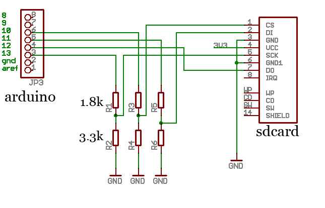
I will nonetheless try to read my micro SD with the SPI mode. I found a circuit example on the following page. The MCU is a 5V-powered ATMEGA16. The SD card is powered through a 3. 3V regulator. The author used resistor dividers to connect the SD card inputs to the ATMEGA16 SPI pins. I bought the same regulator and thought, why not instead try to power the ATMEGA168 directly with 3. 3V thus avoiding the need for a voltage adaptation. The ATMEGA168 datasheet tells me that at 3. 3V the maximum safe frequency is 16MHz so I can keep my current crystal. SPI stands for Serial Peripheral Interface. This interface allows high speed synchronous transfers between a MCU and a peripheral or another MCU. The ATMEGA168 datasheet contains the following figure that highlights the powerful simplicity of this interface: Each side of the interface has a 8-bit shift register.
The left side is the master and the right side is the slave. When the master initiates a transfer to the slave, its SPI clock signal triggers a bit-by-bit copy of each register to the other one. Sending a byte from the master always involves receiving a byte from the slave. The master SPI clock dictates the speed of the transfer. For the ATMEGA168 the maximum speed is Fclk/2. So with a 16 MHz crystal, the maximum theoretical bandwidth is 8Mbit/s, or 1MByte/s. A regular card should support a clock of 25 MHz. Here is some code adapted from the ATMEGA168 datasheet to initialize the SPI interface and do a transfer.
A single function is enough to send or receive a byte or both. void spi_init(void) { /* Set MOSI and SCK output */ DDR_SPI |= _BV(DD_MOSI) | _BV(DD_SCK); DDR_SPI &= ~_BV(DD_MISO); /* Enable SPI, Master, set clock rate fck/128 */ SPCR = _BV(SPE) | _BV(MSTR) | _BV(SPR0) | _BV(SPR1); SPSR = _BV(SPI2X); } uint8_t spi_send_receive_byte(uint8_t byte) { /* Start transmission */ SPDR = byte; /* Wait for transmission complete */ while (!(SPSR & _BV(SPIF); /* Read the received byte */ byte = SPDR; return byte; } For a simple implementation, I started from the AN10406 LPC2000 application note ( Accessing SD/MMC card using SPI on LPC2000 ). I adapted the mmc_init and mmc_read_block functions to be able to read the first block of a SD card. Here is the serial output of reading the sector 63 of my test SD card. It contains a FAT32 MBR with a descriptor for the only available partition NO NAME : spi_init mmc_init send CMD0 send dummy clocks send CMD1 send dummy clocks send CMD16 mmc_init end read block 63 receive block block received 0000: eb58904d53444f53352e300002082400.
X. MSDOS5. 0. $. 0010: 0200000000f800003f00ff003f000000. . . 0020: 99933c001e0f00000000000002000000. <. 0030: 01000600000000000000000000000000. 0040: 000029696561a84e4f204e414d452020. )iea. NO NAME 0050: 2020464154333220202033c98ed1bcf4 FAT32 3. 0060: 7b8ec18ed9bd007c884e028a5640b408 {. |. N. V@. 0070: cd137305b9ffff8af1660fb6c640660f. s. f. @f. 0080: b6d180e23ff7e286cdc0ed0641660fb7. . Af. 0090: c966f7e1668946f8837e16007538837e. f. f. F. ~. u8. ~ 00a0: 2a007732668b461c6683c00cbb0080b9 *. w2f. F. f. 00b0: 0100e82b00e94803a0fa7db47d8bf0ac. +. H. }. }. 00c0: 84c074173cff7409b40ebb0700cd10eb. t. <. t. 00d0: eea0fb7debe5a0f97debe098cd16cd19. }. }. 00e0: 6660663b46f80f824a00666a00665006 f`f;F. J. fj. fP. 00f0: 53666810000100807e02000f852000b4 Sfh. ~. . 0100: 41bbaa558a5640cd130f821c0081fb55 A. U. V@. U 0110: aa0f851400f6c1010f840d00fe4602b4. F. 0120: 428a56408bf4cd13b0f9665866586658 B. V@. fXfXfX 0130: 6658eb2a6633d2660fb74e1866f7f1fe fX. *f3. f. N. f. 0140: c28aca668bd066c1ea10f7761a86d68a. f. f. v. 0150: 56408ae8c0e4060accb80102cd136661 V@. fa 0160: 0f8254ff81c300026640490f8571ffc3. T. f@I. q. 0170: 4e544c44522020202020200000000000 N 🔗 External reference
Related Circuits
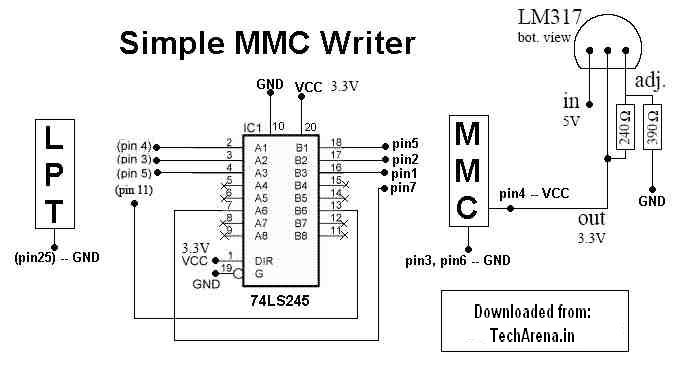
MMC Programmer - Memory Card Unlocker, Portable Devices, Handhelds, palmtops, cellphones, PDAs, pocket organizers, and all those other devices that make computing part of your lifestyle. The MMC Programmer is a specialized device designed for unlocking memory cards, specifically MultiMediaCards...
The block diagram below illustrates the connection of a removable memory card, or MMC card, to its corresponding components. The memory card operates in two signal modes: SD mode and SPI mode. In SD mode, all pins of the...
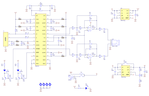
Creating a sound card is no longer a complex task. By utilizing the PCM2702 integrated circuit from Burr Brown / Texas Instruments, it is possible to design a fully functional USB sound card. This sound card can be powered...
A BASIC preprocessor has been developed using Python, enabling code writing without line numbers and allowing the use of labels. This preprocessor automatically assigns line numbers to the code and converts labels accordingly. An example of its application is...
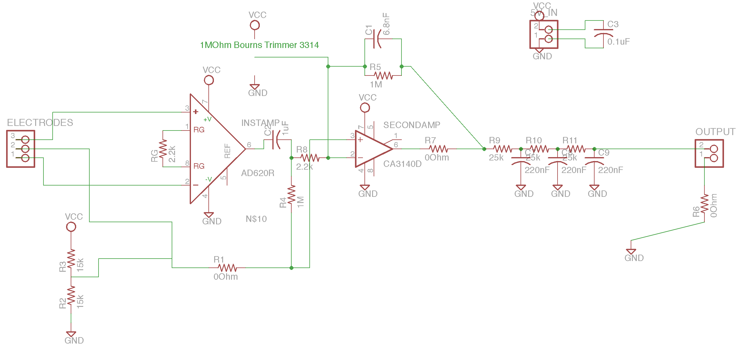
The circuit is based on the designs of Chipstein and Cornell, utilizing an instrumentation amplifier (AD620) to measure the voltage difference between two locations on the body. A second amplifier (CA3140) further amplifies this differential signal. A potentiometer is...
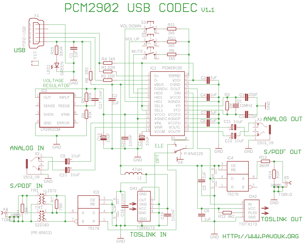
This is a USB sound card featuring the PCM2902 chip. It was designed to test the D/A converters and includes a simple circuit based on the PCM2902. The sound card is equipped with analog input and output, an electrical...