
a simple electrocardiogram board

The circuit design integrates several key components and configurations to achieve accurate bioelectrical signal measurements. The use of the AD620 instrumentation amplifier is critical for amplifying small differential signals, which is essential for applications such as electrocardiography (ECG) where signal levels can be very low. The CA3140 serves as a second amplification stage, ensuring that the signal is sufficiently amplified for further processing. The inclusion of a potentiometer to manage the DC offset is particularly important, as it allows for adjustments based on the unique characteristics of the body and the environment, which can vary significantly.
The virtual ground established by the voltage divider circuit is a clever solution to provide the necessary dual supply voltages for the operational amplifiers while utilizing a single +5V supply from the Arduino. This approach not only simplifies the power supply design but also enhances portability, making the circuit suitable for mobile applications. The strategic placement of low-pass filters effectively minimizes interference from 60 Hz noise, which is prevalent in electrical environments, particularly in clinical settings. The recommendation for detailed frequency response analysis through calculations or simulations highlights the complexity of the circuit's behavior, particularly given the interactive nature of the filters involved.
The integration of the Arduino for both power and data communication streamlines the overall system architecture, allowing for real-time monitoring and data acquisition. This feature is particularly beneficial for applications requiring immediate feedback or logging of bioelectrical signals. The meticulous design considerations, such as the choice of resistors and capacitors in the filtering stages, demonstrate a commitment to achieving high fidelity in signal processing.
Overall, this circuit exemplifies a well-thought-out design for bioelectrical signal measurement, combining effective amplification, filtering, and data acquisition methods to create a robust system suitable for various biomedical applications.Following the same idea as the Chipstein and Cornell designs, the circuit uses an instrumentation amplifier (the AD620) to take the voltage difference between two spots on the body. A second amplifier (the CA3140) amplifies this differential signal. A potentiometer is used to siphon off current from the negative input of the second amplifier, and tuned to remove the DC offset resulting from the inevitable and unpredictable static voltage differences between any two spots on the body: unless removed, the DC offset causes the second amplifier to saturate its output at power or ground. Because we power the amplifiers using only the +5V and ground levels from an Arduino (or other micro-controller board), we need to split the supplies for the amplifiers, which require both a positive and a negative supply line.
To do so, we use a voltage divider circuit to define a virtual ground at 5V/2 = 2. 5V, and then use +5V and Arduino ground as the positive and negative supply lines, respectively. An electrode held at ground electrode is also placed on the body at a third location. Low and high pass filtering are performed in-between amplification steps and during the second amplification step, and then a bank of three low-pass filters follows after amplification to remove additional 60 Hz noise. Those interested in understanding the exact frequency response of the system should do a full calculation (e.
g. , using the Op Amp golden rules and the rules for frequency-dependent impedance of resistors and capacitors) or a Spice simulation, because the filters going into and through the second amplification stage cannot be treated simply as individual high and low pass filters in series. In addition to serving as the power source, the Arduino is also used to sample the amplified signal through one of its analog input ports and to shuttle the signal to a computer over serial.
According to the data sheet: Gain = (49. 9 kOhm / R_G) + 1 where R_G is the gain resistor. Therefore a 49. 4 * (103)/22 = 2. 2 kOhm R_G resistor leads to a gain in the first stage of amplification of around 23. The second amplifier should give an additional factor of around 1 megaOhm/(2. 2 kOhm) = 455. The filtering may remove some frequency components. So the total gain is over 1e4, theoretically. In the below, we`re usually measuring signals of around 1V, which is about 1000x higher than the millivolt-range signals characteristic of ECG, even after filtering, and even using the fabric electrodes. We added zero ohm resistors to allow one trace to hop over another and routed the circuit using Eagle software.
We then milled the traces on a Roland MODELA mini mill using a 1/64 inch end-mill and a 1/32 inch end-mill to cut out the border of the board. To do so, we exported PNG files from Eagle at 2300 dpi resolution and the processed them and sent them to the MODELA using the Fab Modules software.
The top layer was used for the traces and the dimension layer for the board boundary. For the board version we replaced the 6. 8 pF feedback capacitor C1 with a 10 nF capacitor and the 25 kOhm resistors in the filter bank with 22 kOhm resistors, with no negative effect. We removed the electrode assembly from the Zeo and directly soldered wires to the electrodes to serve as inputs to the AD620 instrumentation amplifier.
The green wire here goes to the virtual ground. On the left side of the FabECG, the board receives power and ground from the Arduino through a 5-pin header (connected to Arduino via a small breadboard, here) as well as the three electrode inputs, the middle being the reference electrode held at the 2. 5V virtual ground. The Arduino is connected to my MacBook Pro via a USB cable which provides both power and serial communication.
Disconnect your computer from the wall power and run it off its battery here: do not connect a computer hooked up to the power line to your b 🔗 External reference
Related Circuits
Charging current is about 100+mA, which is the internally-limited maximum current of the LP2951. For those wondering, this is compatible with just about any single-cell li-ion battery since li-ion can generally accept a charging current of up to about...
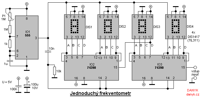
A simple digital frequency meter has various applications, serving as an experiment for beginners, laboratory equipment, or a meter integrated into certain devices. It is ideal for situations where frequency measurement and digital display are required. The frequency meter...
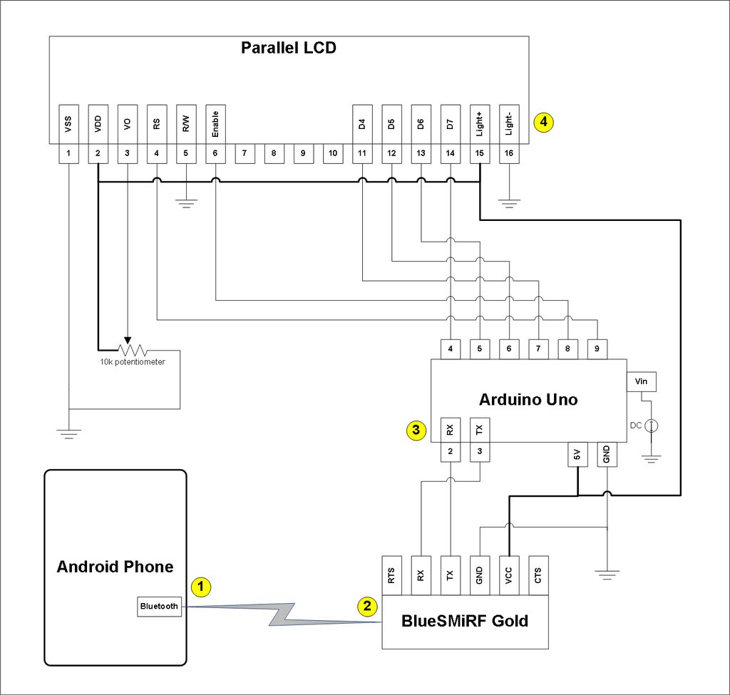
This project involves a modification of the Google Android sample app known as Bluetooth Chat, allowing users to type a message in the Android app and display that same message on an LCD connected to an Arduino Uno. The...
This circuit provides a straightforward method for measuring the voltage of a low-impedance voltage source. It operates as follows: P1, a 1-W potentiometer, acts as a voltage divider in conjunction with resistor R1. The voltage at their junction is...
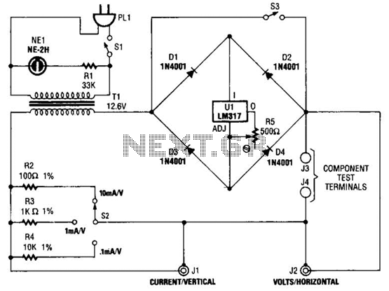
Useful for checking diodes, transistors, triacs, SCRs, resistors, and LEDs, this curve tracer should prove beneficial in the experimenter's lab. It displays the volt-ampere characteristic of a two-terminal device on an oscilloscope. This is a simple block diagram of...
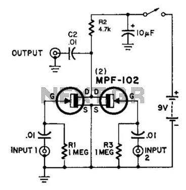
Here is an interesting mixer circuit. With it, signals from audio to high-frequency RF can be effectively combined. Additionally, this circuit provides some gain with a low noise figure. The inputs can accommodate nearly any level or impedance, and...