
Reasonable Car Battery Charger

This automatic battery charger is designed to efficiently charge various types of 12V lead-acid batteries, including flooded, gel, and AGM batteries. The circuit operates by initially delivering a maximum charging current of approximately 4A to the battery until the voltage reaches a predetermined threshold. At this point, the charger switches to a low current float charge mode, which helps maintain the battery's charge without overcharging. This feature allows the charger to remain connected to the battery for extended periods without causing damage.
The circuit includes several key components: resistors (R1, R2, R3, R4, R5, R6, R7, R8, R9), capacitors (C1), diodes (D1, D2, D3), a TRIAC (Q1), an SCR (Q2), a transformer (T1), a fuse (F1), and a switch (S1). The resistors are used for setting various voltage levels and current limits within the circuit. The potentiometer (R2) is adjustable to set the proper finish charge voltage, which is critical for different battery types. Flooded and gel batteries typically require a finish charge voltage of 13.8V, while AGM batteries may require a higher voltage of 14.5V to 14.9V.
The charger also incorporates an LED indicator (D4) to signal when the battery is fully charged, providing a visual confirmation to the user. The transformer (T1) is essential for stepping down the AC mains voltage to the required 12V for charging. It is important to select a transformer with a primary voltage rating suitable for the local mains supply (e.g., 120V or 220V) and a secondary voltage of around 12V. For applications requiring higher voltages, a transformer with a secondary voltage of 16V to 18V can be used, especially for racing batteries.
To ensure safe operation, a 3A fuse (F1) is included to protect the circuit from overcurrent conditions. The use of a heatsink for the TRIAC (Q1) is recommended to dissipate heat generated during operation, and if the circuit is enclosed in a case, a small fan may be necessary to maintain optimal operating temperatures.
When setting up the charger, the potentiometer should be adjusted to the midpoint, and the charger should be powered on before connecting the battery. A voltmeter can be used to monitor the battery voltage, allowing for precise adjustment of the potentiometer until the LED glows steadily, indicating that the charger is correctly set for the specific battery type.
It is crucial to disconnect the battery from the output when the circuit is powered off to prevent slow discharge of the battery through the charger circuitry. Proper attention to these details will ensure the longevity and effectiveness of the battery charging process.This charger will charge any 12V lead acid battery including flooded, gel and AGM. It is fully automatic and will charge at a rate up to about 4A until the battery voltage reaches a preset point at which it will switch to a very low current float charge. If the battery voltage drops again the charger will begin charging until the voltage once again reaches the cut off point.
In this way it can be left connected to a battery indefinitely to maintain full charge without causing damage. An LED indicates when the battery is fully charged. R1, R3 2 330 Ohm 1/4W Resistor R2 1 100 Ohm 1/4W Pot R4, R5, R7, R8 4 82 Ohm 2W Resistor R6 1 100 Ohm 1/4W Resistor R9 1 1K 1/4W Resistor C1 1 220uF 25V Electrolytic Capacitor D1 1 P600 Diode Any 50V 5A or greater rectifier diode D2 1 1N4004 Diode 1N4002, 1N4007 D3 1 5.6V Zener Diode D4 1 LED (Red, Green or Yellow) Q1 1 BT136 TRIAC Q2 1 BRX49 SCR T1 1 12V 4A Transformer See Notes F1 1 3A Fuse S1 1 SPST Switch, 120VAC 5A MISC 1 Wire, Board, Heatsink For U1, Case, Binding Posts or Alligator Clips For Output, Fuse Holder Notes R2 will have to be adjusted to set the proper finish charge voltage. Flooded and gel batteries are generally charged to 13.8V. If you are cycling the battery (AGM or gel) then 14.5V to 14.9V is generally recommended by battery manufacturers.
To set up the charger, set the pot to midway, turn on the charger and then connect a battery to it's output. Monitor the charge with a voltmeter until the battery reaches the proper end voltage and then adjust the pot until the LED glows steadily.
The charger has now been set. To charge multiple battery types you can mount the pot on the front of the case and have each position marked for the appropriate voltage. Q1 will need a heatsink. If the circuit is mounted in a case then a small fan might be necessary and can generally be powered right off the output of D1.
T1 is a transformer with a primary voltage appropriate to your location (120V, 220V, etc.) and a secondary around 12V. Using a higher voltage secondary (16V-18V) will allow you to charge 16V batteries sometimes used in racing applications.
If the circuit is powered off, the battery should be disconnected from it's output otherwise the circuit will drain the battery slowly. 🔗 External reference
Related Circuits
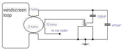
If you do not like the whip antenna on your car, you may try this alternative circuit. A one-turn loop is installed in the windscreen of the car, keeping possibly away from the metal structure of the car. This...
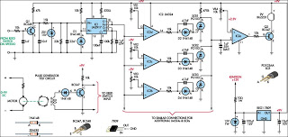
The above pictured schematic diagram is just a standard constant current model with a added current limiter, consisting of Q1, R1, and R4. The moment too much current is flowing biases Q1 and drops the output voltage. The output...
When driving, it can be difficult to gauge the speed of a vehicle, particularly on straight highways. If the vehicle exceeds a safe speed, it may lead to accidents. Therefore, a Car Speed Alarm circuit is necessary to alert...
This circuit employs the widely used and easily accessible LM3914 integrated circuit (IC). The LM3914 is straightforward to operate, does not require external voltage regulators due to its built-in voltage regulation, and can be powered by a variety of...
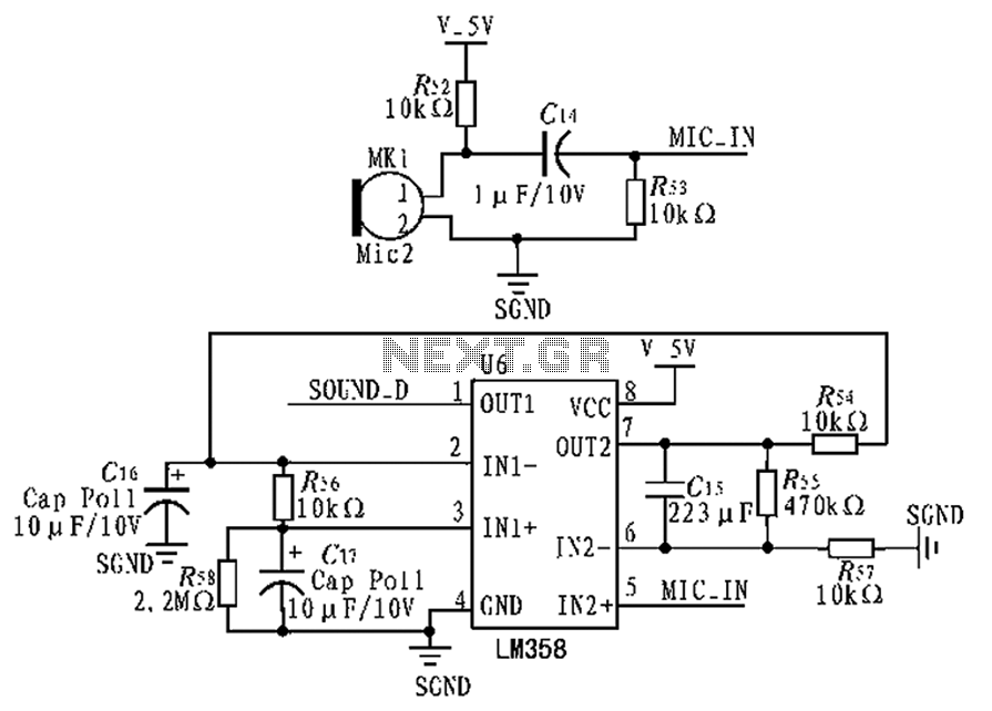
The circuit diagram focuses on the research and design features applied to mobile robots. The design considers small size, low power consumption, and ease of movement, catering to home users with a user-friendly display interface. For speech recognition, a...
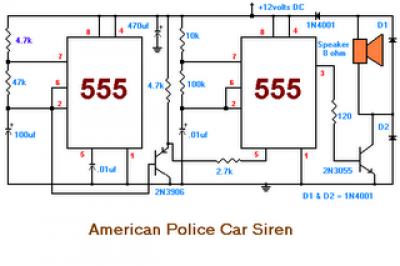
The second circuit simulates the siren of an American police car. It utilizes two 555 timers. The 555 timer on the right is configured as an alarm tone generator, while the second 555 timer on the left operates as...