
Real-time speech recognition system application circuit in family care robot

The described circuit diagram serves as a foundational element for the functionality of mobile robots, particularly in the realm of speech interaction. The design prioritizes compactness and efficiency, ensuring that the robot can operate effectively within a domestic environment.
The processor at the heart of the speech recognition system is critical, as it executes complex algorithms that translate audio signals into actionable commands. This processor is typically a microcontroller or a dedicated digital signal processor (DSP) capable of handling real-time audio processing tasks. The efficiency of the speech recognition algorithm directly influences the robot's responsiveness and accuracy in understanding voice commands.
The voice acquisition circuit, which includes a microphone and associated circuitry, is designed to capture sound waves from the environment. This circuit may incorporate noise filtering techniques to enhance the clarity of the audio signal, thereby improving the recognition accuracy. The microphone converts acoustic energy into electrical signals, which are then processed by the processor.
The voice output circuit is equally important, as it transforms the processed data back into audible sound. The power amplifier amplifies the signal sufficiently to drive a speaker, ensuring that the robot can communicate effectively. The choice of speaker and amplifier affects the quality and volume of the output sound, which is essential for user interaction.
In summary, the schematic design for the mobile robot integrates these components into a cohesive system that enables voice input, processing, and output. The careful selection and arrangement of these elements are crucial for creating a responsive and interactive robotic system that meets user needs in a home environment. Circuit diagram in the research and design features, are applied on the mobile robot. Therefore the study design systems to take into account small size, low power, easy to mov e character, and home users need to have to facilitate the operation of the display-friendly interface. For the part of speech recognition, the need to use a processor for processing speech recognition algorithm, the voice collecting circuit and voice output circuit.
Wherein the processor of the speech recognition algorithm is responsible for operation of the arithmetic operation processing as the brain of the robot; voice acquisition circuit is responsible for collecting the external sound signal, corresponding ears of the robot; is responsible for the sound output voice output circuit words, the robot is equivalent to the mouth. The schematic design is used in mobile robots, requiring voice input, voice recognition processing and output.
For voice input acquisition, as used herein, a sound sensor, microphone and peripheral circuits. For voice output section, the use of a power amplifier used in conjunction speaker. Shown in the schematic design of the part of speech.
Related Circuits
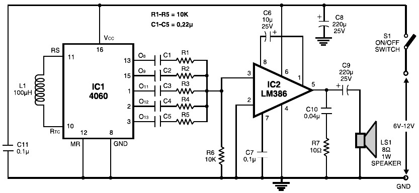
The circuit is built around the popular CMOS oscillator-divider IC 4060 and a small audio amplifier LM386. The IC 4060 functions as a multitone generator. A 100 H inductor is used at the input of the IC 4060, allowing...
At low output power, up to 18 W, the device functions as a standard BTL amplifier. When a greater output voltage swing is necessary, the internal supply voltage is increased using external electrolytic capacitors. This momentarily elevated supply voltage...
Implementing peak-detector circuits is straightforward with the CA3130, as illustrated in the schematic diagram of this circuit. The figure below presents the schematic diagram. The CA3130 is a high-performance operational amplifier that is well-suited for peak detection applications due to...
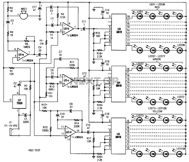
The microphone input, MIC1, is connected through capacitor C3 and resistor R4 to the inverting amplifier U2-a, where the gain of U2-a is adjusted by potentiometer R5. The output from U2-a is passed through capacitor C4 to the remaining...
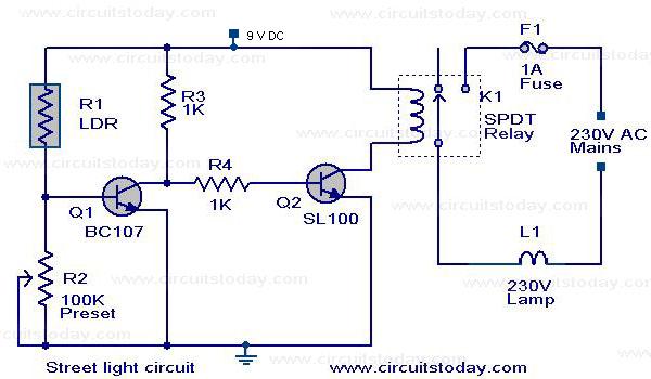
The circuit diagram of an Automatic Street Light Controller Circuit is explained in this post. The Automatic Street Light Controller Circuit is designed to automatically turn on street lights at dusk and turn them off at dawn. This functionality is...
The most important part of this 88-108 transmitter is the Colpitts oscillator. Capacitors C3, C4, C5, C6, diodes CD1 and CD2, and inductor L1 determine the transmission frequency. The RF oscillator... The Colpitts oscillator is a type of electronic oscillator...