
RECEIVER BUILDING BLOCKS

The described amplifier circuit is a medium power RF amplifier designed to provide a gain of approximately 20 dB with a bandwidth of 100 MHz and a noise figure of about 7 dB. This performance makes it particularly suitable for applications in the front end of HF receivers or as a post-mixer amplifier following a diode mixer.
The key component of this amplifier is a UHF transistor, such as the 2N5109, 2N3866, or 2N4427. These transistors are selected for their ability to operate effectively within the UHF frequency range while providing the necessary gain and power handling capabilities. The transistor requires a small clip-on heatsink to manage thermal dissipation, ensuring reliable operation under varying conditions.
The output stage of the amplifier employs an 8-turn bifilar wound transformer on a ferrite core. This transformer configuration is essential for impedance matching and maximizing power transfer from the transistor to the load. The bifilar winding technique helps reduce the effects of parasitic capacitance and improves the overall efficiency of the amplifier.
In the schematic, the transistor is typically configured in a common-emitter arrangement to achieve the desired gain. Biasing resistors are employed to establish the appropriate operating point for the transistor, ensuring linear amplification across the specified bandwidth. Coupling capacitors are used at the input and output to block DC while allowing AC signals to pass through, maintaining the integrity of the signal chain.
Power supply decoupling capacitors may also be included to filter out any high-frequency noise that could affect the performance of the amplifier. Proper grounding and layout techniques are crucial to minimize interference and ensure stable operation. The overall design should consider component placement and trace routing to reduce inductive and capacitive coupling, which can degrade performance at high frequencies.
This amplifier design is an effective solution for enhancing signal strength in RF applications, providing the necessary gain and bandwidth for optimal performance in communication systems.This amplifier has about 20dB of gain, bandwidth of 100MHz and noise figure of about 7dB. The output transformer is 8 turns bifilar wound on a ferrite core. Use a medium power UHF transistor 2N5109, 2N3866, 2N4427 or similar. The transistor will need a small clip on heatsink. This amplifier is suitable for use in the front end of a HF receiver or as a post mixer amplifier following a diode mixer (see below.) 🔗 External reference
Related Circuits
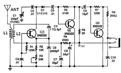
This circuit is essentially a crystal radio equipped with an audio amplifier that demonstrates considerable sensitivity, successfully receiving multiple strong stations in the Los Angeles area using a minimal 15-foot antenna. Employing a longer antenna can enhance signal strength;...

This design features a simple yet effective receiver with good sensitivity and selectivity. The circuit utilizes a compact three-transistor regenerative receiver with fixed feedback, primarily based on the BC549 transistor. The tuned circuit is intended for medium wave frequencies...
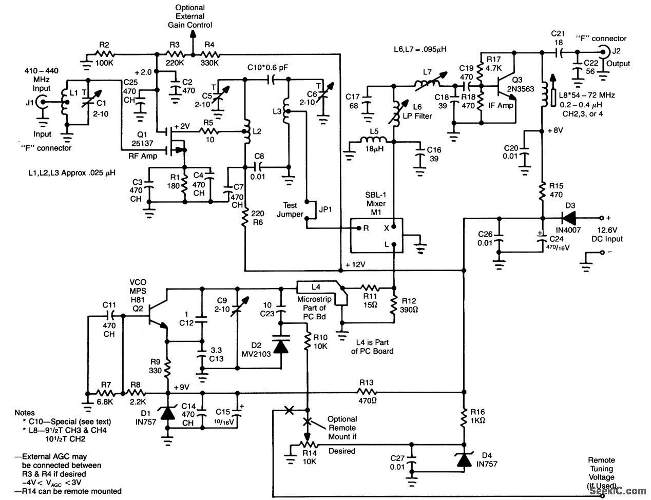
L1, Q1, L2, and L3 form an RF amplifier stage that drives M1, a doubly balanced mixer. Q4 serves as a local oscillator stage operating in the 375-MHz range. Signals in the 420 to 450-MHz range from Q1 are...
All coils are designed using an inch diameter PVC pipe with 20-gauge insulated hookup wire. L1 requires 6 turns, while L2 requires 14 turns. Additional turns can be added or subtracted from L1 or L2 (or C2 can be...
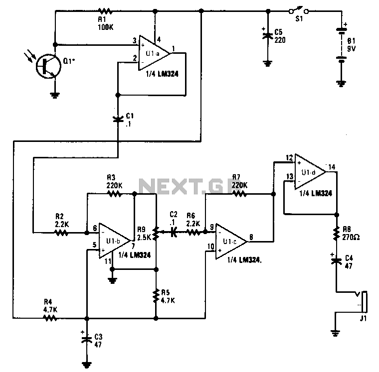
Infrared emissions detected by Q1 are transmitted through U1A to U1B, which amplifies the signal by a factor of 100. The amplified output of U1B is sent to U1C through R9, C2, and R6. Potentiometer R9 functions as a...
This is a high-performance radio receiver antenna amplifier designed for the entire VHF broadcast and PMR band (100-175 MHz) that can be successfully constructed without... This radio receiver antenna amplifier is engineered to enhance the signal quality and reception capabilities...