
Micro Power AM Receiver circuit

The circuit design utilizes a straightforward crystal radio architecture paired with an audio amplification stage to enhance audio output. The antenna's length directly influences the reception quality, with the trade-off between signal strength and selectivity being a critical consideration. The inductor's design, featuring taps for optimal diode connection, allows for user adjustments to maximize performance based on local signal conditions. The choice of diode is pivotal; germanium diodes are favored for their lower forward voltage drop compared to silicon diodes, making them more effective in weak signal scenarios.
The operational amplifier stages are configured to provide both buffering and amplification, ensuring that the audio signal is adequately processed for headphone output. The use of capacitors for signal filtering is essential to eliminate unwanted frequencies while allowing the desired audio signal to pass through. Furthermore, careful attention to resistor values and configurations is necessary to maintain the desired operating conditions for the amplifying stages, ensuring reliable and consistent performance.
Overall, this circuit exemplifies a practical approach to receiving AM radio signals with enhanced audio output, making it an excellent project for enthusiasts interested in analog electronics and radio technology.This is basically a crystal radio with an audio amplifier which is fairly sensitive and receives several strong stations in the Los Angeles area with a minimal 15 foot antenna. Longer antennas will provide a stronger signal but the selectivity will be worse and strong stations may be heard in the background of weaker ones.
Using a long wire antenn a, the selectivity can be improved by connecting it to one of the taps on the coil instead of the junction of the capacitor and coil. Some connection to ground is required but I found that standing outside on a concrete slab and just allowing the long headphone leads to lay on the concrete was sufficient to listen to the local news station (KNX 1070).
The inductor was wound with 200 turns of #28 enameled copper wire on a 7/8 diameter, 4 inch length of PVC pipe, which yields about 220 uH. The inductor was wound with taps every 20 turns so the diode and antenna connections could be selected for best results which turned out to be 60 turns from the antenna end for the diode.
The diode should be a germanium (1N34A type) for best results, but silicon diodes will also work if the signal is strong enough. The carrier frequency is removed from the rectified signal at the cathode of the diode by the 300 pF cap and the audio frequency is passed by the 0.
1uF capacitor to the non-inverting input of the first op-amp which functions as a high impedance buffer stage. The second op-amp stage increases the voltage level about 50 times and is DC coupled to the first through the 10K resistor.
If the pairs of 100K and 1 Meg resistors are not close in value (1%) you may need to either use closer matched values or add a capacitor in series with the 10K resistor to keep the DC voltage at the transistor emitter between 3 and 6 volts. Another approach would be to reduce the overall gain with a smaller feedback resistor (470K). High impedance headphones will probably work best, but walkman stereo type headphones will also work.
Circuit draws about 10 mA from a 9 volt source. Germanium diodes (1N34A) types are available from Radio Shack, #276-1123. 🔗 External reference
Related Circuits
This project involves outdoor LED solar garden lights, which function as an automatic garden lighting system utilizing a light-dependent resistor (LDR) and a 6V/5W solar panel. During daylight hours, the internal rechargeable 6 Volt sealed lead-acid (SLA) battery is...
To commemorate the hundredth design posted on this website and to meet the requests of numerous correspondents desiring a more powerful amplifier than the 25W MosFet, a 60 - 90W high-quality power amplifier design is presented. The circuit topology...
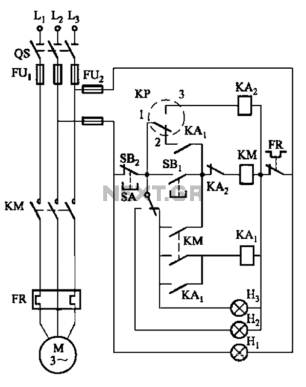
An air compressor is commonly utilized in electrical equipment factories and is typically controlled by electrical contacts. The circuit diagram is depicted in Figure 5-1. The circuit allows for both automatic and manual operation. In the diagram, KP represents...
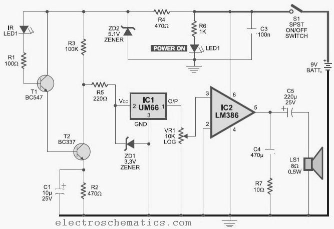
This infrared detector is capable of detecting the presence of modulated infrared signals in its vicinity from various electronic sources, such as an IR handheld remote. The infrared detector operates by utilizing a photodetector that is sensitive to infrared light....
This type of sensor switch is ideal for creating touch-operated bells and buzzers in small toys, which function for a limited duration before automatically shutting off. The trigger's input impedance is very high, allowing the touch sensor switch to...
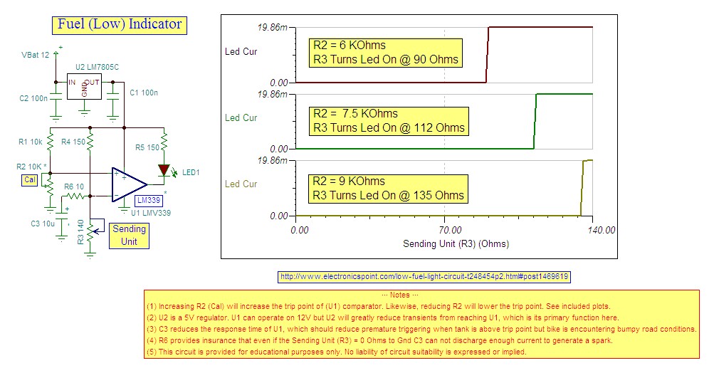
Research indicates that the sender will register a resistance of 100 ohms when the fuel tank is empty, making a trigger reading of 80 ohms optimal. The fuel gauge sender is a critical component in monitoring the fuel level within...