
Regulation with transistors


Circuit 4 probably my favourite of the four. Here R1 is driven from the In voltage so that the zener is always biased - this removes the problem of the two stable states - on and off. But there's nothing to stop you biasing the zener from the output if you wish a trip! No formula here as the output voltage if Vz, more or less. The emitter voltage of Tr2 will be Vbe less than Vz and the output will be stable one diode voltage above that. Adding the extra diode D2 is interesting: with it present a re-entrant power supply can be built. See Simple regulated power supply with overcurrent trip for a practical circuit. In this, the circuit has been turned on its head, to stabilize the negative rail, so uses a PNP series pass instead of an NPN, and it also uses a Darlington transistor instead of the single pass transistor here, but it's the same configuration.
Voltage regulators utilizing two transistors can be categorized based on their configuration and functionality. The primary configurations discussed are based on the arrangement of the error amplifier and the series-pass transistor. In these circuits, the series-pass transistor is responsible for controlling the output voltage, while the error amplifier monitors the output and adjusts the base current to the series-pass transistor accordingly.
Circuit 1 features a reference zener diode placed in the emitter of the error amplifier, allowing for a stable output voltage that is influenced by the zener voltage minus the base-emitter voltage drop (Vbe) of the transistor. Circuit 2, on the other hand, positions the zener in the base of the error amplifier, providing a different method of voltage regulation.
Circuit 3 introduces a bistable configuration where the absence of output voltage results in no base voltage for the second transistor (Tr2), effectively rendering the circuit stable in the off state. This configuration can be particularly useful for applications requiring a power supply that can be tripped.
Circuit 4 enhances the design by ensuring that the zener diode is always biased, thereby eliminating the dual stable states of on and off. The output voltage closely aligns with the zener voltage (Vz), with the emitter voltage of Tr2 being Vbe lower than Vz, resulting in a stable output. The inclusion of an additional diode (D2) allows for the creation of a re-entrant power supply, which can be particularly advantageous in applications requiring overcurrent protection.
In summary, the described circuits illustrate various methods of implementing voltage regulation using two transistors, each with unique advantages and configurations suitable for different applications in electronic design.This page discusses the various ways that a voltage regulator can be made using two transistors. If one of these transistors is the series-pass element, then the other must be the error amplifier, so there is a distinct limit to the number of possible circuits. If we also specify that we are only interested in regulators that control the positive supply, then there are only four basic configurations to discuss.
These are probably the most obvious of the four, to most readers. I guess really calling them two transistor circuits is possibly stretching things as they both show a current source to supply base current to the series-pass transistor. Yes, if conditions are right, you can use a resistor here. Circuit 1 has the reference zener in the emitter of the error amplifier. Circuit 2 has the reference zener in the base. This is rather more interesting. However, consider the situation where there is no output voltage. Clearly in this case there can also be no voltage on the base of Tr2 which therefore cannot conduct. So the circuit is quite stable in the off state. It is in fact a 'bistable' - one stable state is off and the other is regulating with an output voltage of Now this can be quite useful - if you want a tripped power supply. See Switched Power Supplies where this is the basis of the third circuit. Notice also that the term (Vz-Vbe) occurs in the formula. If you chose the zener diode correctly, its temperature coefficient can broadly cancel out the tempco of the transistor and the output voltage will be better stabilised against ambient temperature changes.
Circuit 4 Probably my favourite of the four. Here R1 is driven from the In voltage so that the zener is always biased - this removes the problem of the two stable states - on and off. But there's nothing to stop you biasing the zener from the output if you wish a trip! No formula here as the output voltage if Vz, more or less. The emitter voltage of Tr2 will be Vbe less than Vz and the output will be stable one diode voltage above that.
Adding the extra diode D2 is interesting: with it present a re-entrant power supply can be built. See Simple regulated power supply with overcurrent trip for a practical circuit. In this, the circuit has been turned on its head, to stabilize the negative rail, so uses a PNP series pass instead of an NPN, and it also uses a Darlington transistor instead of the single pass transistor here, but it's the same configuration. 🔗 External reference
Related Circuits
When there is a need to amplify audio signals from various sources before they reach a custom amplifier, a preamplifier (or preamp) is typically employed. This document suggests a specific circuit that is interesting due to its use of...
The monostable flip-flop is an electronic circuit that is used to produce a single pulse each time it is triggered. Sometimes, this circuit is referred to as a "one-shot." The monostable flip-flop operates in two states: a stable state and...
The LTC3731H is a linear three-phase step-down voltage regulation power control unit from the company, capable of driving N-channel MOSFETs. It operates within a temperature range of up to 140°C and supports a control frequency of up to 600...
This power supply is based on the 7805 IC regulator, which provides a regulated output voltage ranging from 5 V to 15 V DC, adjustable by a preset resistor. The maximum output current of this power supply is 350...
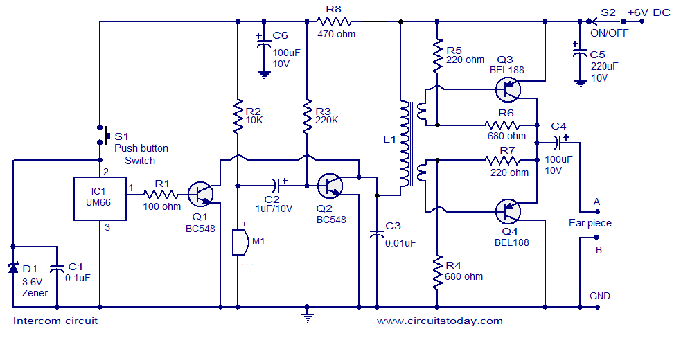
A straightforward intercom circuit designed using transistors. It does not require a changeover switch and can be used similarly to a telephone. This intercom circuit utilizes transistors to facilitate communication between two or more stations without the need for complex...
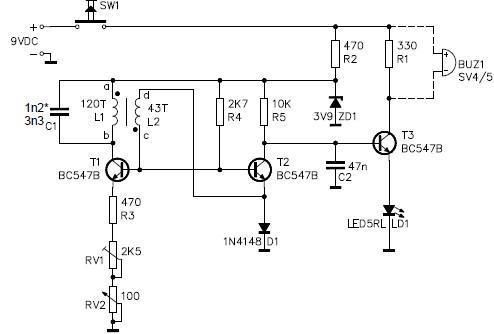
This metal detector circuit project is a simple design based on common electronic components. It utilizes transistors to provide a visual indication through an LED and an acoustic signal to alert users when metal is detected. To calibrate the...