
Relay Timer switch circuit

The circuit described employs a 555 timer IC configured in a monostable mode to create a delay function. When the circuit is powered with a +12V supply, the timer initiates a countdown for 100 seconds, after which it energizes relay RL1, allowing it to close its contacts and complete a secondary circuit.
For the timer circuit depicted in Figure 2, the 555 timer can be adjusted to provide two selectable time ranges. The first range allows for delays from 6 to 60 seconds, while the second range extends the delay from 1 to 10 minutes. This is achieved by incorporating variable resistors (potentiometers) and capacitors that determine the timing intervals.
The configuration of the 555 timer includes a resistor connected to the discharge pin and a capacitor connected to the threshold pin, which sets the timing period. The output from the 555 timer drives the relay coil of RL1, ensuring that it remains activated only for the duration set by the timing components.
In summary, this relay timer circuit provides a versatile solution for applications requiring delayed activation, leveraging the reliability of the 555 timer IC to achieve precise timing control over the relay operation.A 100 second delayed turn ON relay RL1 switch, if plug power +12V in circuit. In Fig. 2 see a two range 6-60 second and 1-10 minute auto turn off relay timer circuit, with 555. 🔗 External reference
Related Circuits
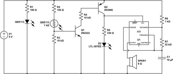
This circuit detects when a tube is empty and pulses a piezo buzzer at 5-second intervals. It is currently operational with a 5V supply on a breadboard but needs to be adapted for a 12V supply from a wall...
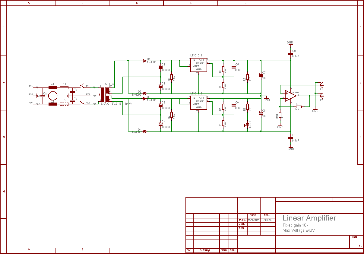
The aim of this project was to develop a linear analogue amplifier designed for laboratory use. This amplifier has to realise a voltage amplification of 10x and is intended to amplify function generator signals for tests. Power supply requirements:...

The circuit incorporates components Q, C, and ZD, which are responsible for the bias and buffer stages. Its primary objective is to ensure stable MOSFET gate operation and provide an offset voltage through a voltage buffer amplifier stage with...
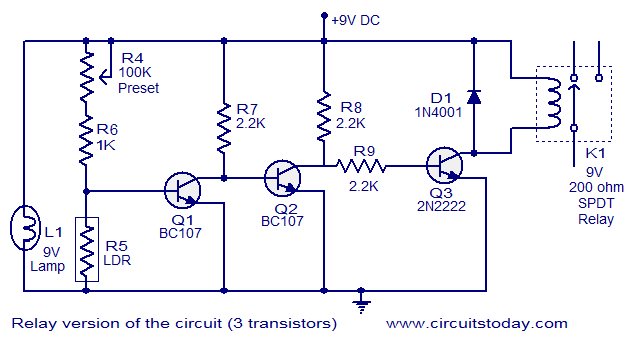
This document describes a simple fire alarm circuit utilizing a Light Dependent Resistor (LDR) and lamp combination for fire detection. The alarm activates by detecting smoke generated during a fire. When smoke is present, the circuit triggers an audible...
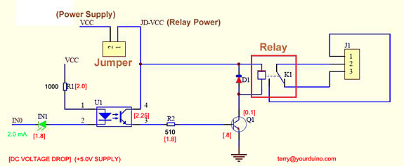
Control a relay from an Arduino-compatible board. When attempting to activate the relay from the Arduino, it takes at least a second to close, and sometimes it does not close at all. Digital pin 2 of the Arduino is...
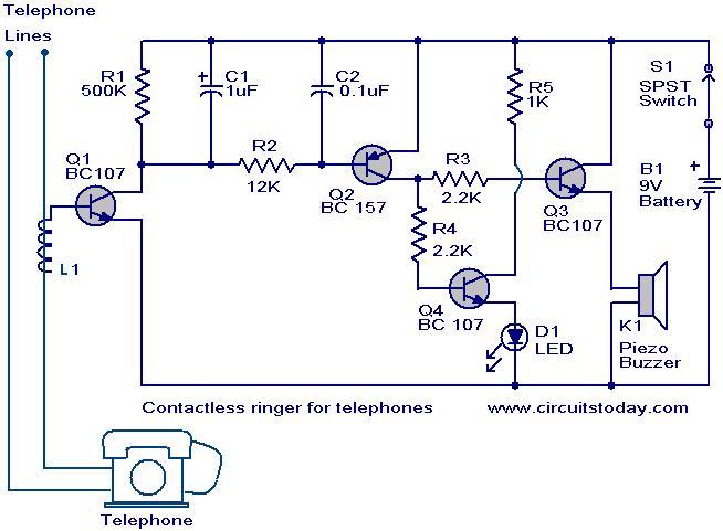
The contactless telephone ringer circuit is designed to produce an audible ring and a visual indication when a call is received. Its primary advantage lies in the absence of direct contact between the telephone line and the circuit, which...