
Relay Toggle Circuit Using a 555 Timer circuit

The described circuit utilizes a 555 timer in a bistable configuration, allowing it to function as a toggle switch for a relay. The relay can control larger loads and is often used in applications where electrical isolation is needed between the control circuit and the load.
In this circuit, the two 10K resistors connected to pins 2 and 6 ensure that these pins are biased at half the supply voltage, which is essential for the proper operation of the timer. When the button is pressed, it momentarily connects the capacitor voltage to the trigger input (pin 2). This causes the timer to switch its output state.
The 100K resistor plays a crucial role in controlling the charging time of the capacitor. When the output of the 555 timer is high, the capacitor charges through this resistor, leading to a gradual increase in voltage across the capacitor. Once the voltage across the capacitor reaches a certain threshold, the output of the timer switches to low, allowing the capacitor to discharge. This cycle can repeat with each button press, effectively toggling the state of the relay.
The relay, connected to the output pin, can be used to switch on or off additional circuits or devices, providing a practical application for the timer circuit. Care should be taken to select a relay that can handle the load current and voltage requirements of the connected device. Additionally, appropriate flyback diodes should be used across the relay coil to protect the timer from voltage spikes generated when the relay is de-energized.
This configuration offers a simple yet effective method for creating a toggle switch with the added benefits of isolation and control over higher power devices.This 555 timer circuit toggles a relay when a button is pressed. Pins 2 and 6, the threshold and trigger inputs, are held at 1/2 the supply voltage by the two 10K resistors. When the output is high, the capacitor charges through the 100K resistor, and discharges when the output is low.
When the button is pressed, the capacitor voltage is applied to pins 2 and 6 which causes the output to change to the opposite state.. 🔗 External reference
Related Circuits
The EUA2032 is a high-efficiency, 2.5W mono class-D audio power amplifier. A newly developed filterless PWM modulation architecture further reduces EMI and THD+N, as well as eliminates the LC output filter, thereby reducing the external component count, system cost,...
The circuit described below is notable for its low power consumption. With a 9V input and no load at the output, it draws only 50 mA, which is significantly lower than the quiescent current of a 78L05 regulator. The...
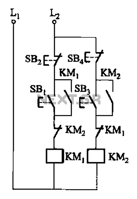
A, B, and two electric motors allow simultaneous operation through interlock control. The two motors can be connected in series with each other using normally closed contacts in the respective coil circuit. The circuit design facilitates the interlocking operation of...
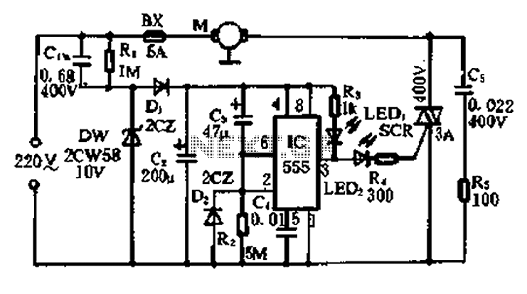
A 5-minute circuit can continue to operate during a power outage, providing protection for the refrigerator. The refrigerator power protection circuit, designated as 1136, includes a power transformer that converts 220V voltage through a rectifier bridge (VD1). This setup...
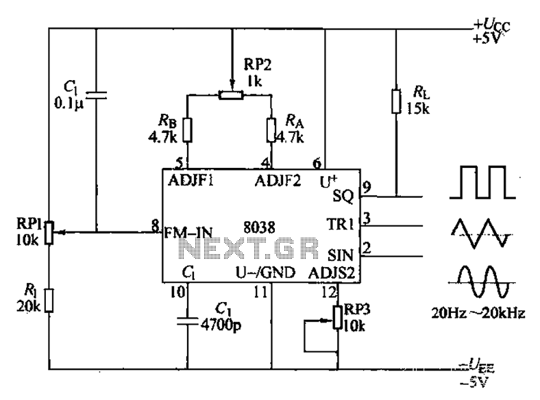
The audio function generator integrated circuit ICL8038 is capable of producing square waves, triangle waves, and sine waves. The electrical resistance and potentiometer RP1 are utilized to determine the 8-pin DC potential Ua, which is typically set to 2Ucr/3....
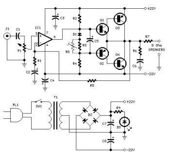
Proper grounding is essential for eliminating hum and ground loops. Connect the ground terminals of J1, P1, C2, C3, and C4 to the same point. Connect C6 to the output ground. An audio amplifier is an electronic device that...