
18W Audio Amplifier Circuit

An audio amplifier circuit typically consists of several key components that work together to boost the audio signal. The grounding scheme is crucial; improper grounding can lead to unwanted noise and interference. The ground connections for components such as audio jacks (J1), power connectors (P1), and capacitors (C2, C3, C4) should all converge at a single ground point to ensure a common reference level, thus minimizing the risk of ground loops and hum.
The audio amplifier itself may utilize an integrated circuit (IC) designed specifically for audio applications. This IC can accept low-level audio inputs from various sources, such as MP3 players or other audio devices, and amplify them to a level suitable for loudspeakers. The design should incorporate capacitors like C6 to filter out any noise from the power supply and stabilize the output.
The output stage of the amplifier is critical, as it must be capable of delivering sufficient power to drive speakers effectively. This stage may involve additional components such as transistors or MOSFETs, which can handle high current loads, ensuring that the amplifier can produce output power in the range of watts required for typical loudspeakers.
The power supply for the amplifier, in this case, is a 9V battery, which provides the necessary voltage for the circuit. The choice of power supply affects the overall performance and efficiency of the amplifier. The circuit design should also include appropriate protection mechanisms, such as fuses or thermal shutdown features, to prevent damage during operation.
In summary, a well-designed audio amplifier circuit requires careful attention to grounding, component selection, and power management to achieve optimal performance in amplifying audio signals for playback through loudspeakers.A correct grounding is very important to eliminate hum and ground loops. Connect to the same point the ground sides of J1, P1, C2, C3 & C4. Connect C6 to the output ground. An audio amplifier is an electronic amplifier that amplifies low-power audio signals (signals composed primarily of frequencies between 20 - 20 000 Hz, the human range of heari ng) to a level suitable for driving loudspeakers and is the final stage in a typical audio playback chain. The preceding stages in such a chain are low power audio amplifiers which perform tasks like pre-amplification, equalization, tone control, mixing/effects, or audio sources like record players, CD players, and cassette players.
Most audio amplifiers require these low-level inputs to adhere to line levels. While the input signal to an audio amplifier may measure only a few hundred microwatts, its output may be tens, hundreds, or thousands of watts. More explanation about power audio amplifier can be found at wikipedia. org This is the video tutorial about how to build a realy simple headphone amplifier. The circuit powered with 9V battery and use an IC to amplify the input signal from mp3 player. 🔗 External reference
Related Circuits
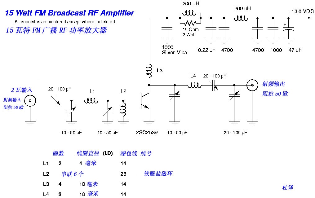
This FM broadcast RF amplifier is constructed using the 2SC2539, which is a silicon NPN epitaxial planar type transistor designed for RF power amplifiers in the VHF band. The FM broadcast RF amplifier utilizing the 2SC2539 transistor operates effectively within...
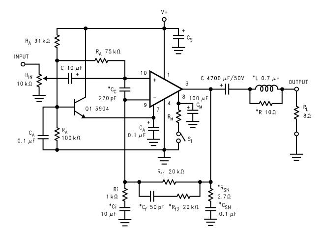
The LM2876 audio power amplifier circuit can be designed as a simple, high-efficiency audio amplifier capable of delivering 40W of continuous average power to an 8-ohm load with a total harmonic distortion plus noise (THD+N) of 0.1% from 20Hz...
An oscillator is a mechanical or electronic device that operates based on the principles of oscillation. Oscillators serve as fundamental building blocks upon which the entire structure of electronics and computers is established. An article is available that explains...
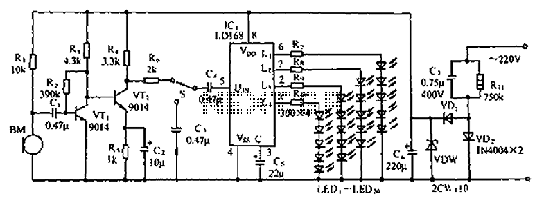
The circuit depicted in the figure involves the LD168, which functions as a sound level indicator for tape recorder speakers. It features four outputs capable of directly driving multiple light-emitting diodes. Additionally, the device can be activated by a...
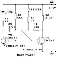
This circuit activates an alarm when tilted beyond a specific angle. Commonly used in various electronic devices, such as heaters, tip-over protection circuits can either shut off the device or trigger an alert. In this case, the circuit is...

The circuit illustrated below represents a simple thermometer circuit based on the LM335 temperature sensor. This circuit comprises two main components: the LM335 sensor and its adjustment circuitry. The output from the LM335 generates a voltage of 10 millivolts...