
relay triac

The conversion from a relay to a triac in this design presents a viable option for controlling a nichrome wire heater operating at 120V with a resistance of 60 ohms. Triacs are advantageous for AC control applications due to their ability to switch and control power in both directions of the AC cycle.
In Method 1, the circuit design involves integrating a transistor (T1) to control the gate of the triac. The neutral of the 120V AC line is connected to the circuit ground, allowing for a common reference point. The resistor connected to the gate of the triac is crucial for limiting the current and ensuring proper triggering of the triac. The nichrome wire is connected in series with the triac, enabling the triac to control the power delivered to the nichrome wire directly. The collector of T1, connected to the +12V supply, allows for a low-voltage control signal to manage the higher voltage triac operation.
In Method 2, the design opts for electrical isolation between the control and power circuits. By utilizing an opto-isolator, the control signal from T1 can safely operate the triac without a direct electrical connection to the high-voltage side. This method enhances safety and reduces the risk of noise interference from the high-voltage circuit affecting the control logic. The opto-isolator transmits the control signal via a light beam, providing a reliable way to trigger the triac while maintaining separation from the primary circuitry.
Both methods require careful consideration of component ratings, particularly the triac, which must be capable of handling the 120V AC voltage and the current flowing through the nichrome wire. Additionally, thermal management should be addressed, as both the triac and the nichrome wire will generate heat during operation. Proper heat sinks and thermal interfaces may be necessary to ensure reliable operation and longevity of the components. Overall, transitioning from a relay to a triac can enhance the efficiency and responsiveness of the heating circuit while maintaining safety and operational integrity.How hard it would be to convert the relay in this design to a triac It switches a 120v Ni-chrome wire that is 60ohms. Thanks for any help you can offer. Your right i apologize. The ic powers off of a 12v transformer. However there is a 120v neutral and line onboard that feeds a 12v voltage reg ulator. Here is the proposed circuit. It`s still a work in progress. Method 1) Connect the 120 volt neutral to the circuit ground, then use T1 to send current through a resistor to the gate of a triac and connect one end of the nichrome to the 120 circuit and the other end to the anode of the triac. The third terminal of the triac goes to ground. The collector of T1 goes to the +12 supply. method 2) Don`t connect the 120 neutral to the circuit ground. Have T1 drive an opto-isolator and have that drives a triac. The nichrome power circuit will stand seperate from your primary circuitry, connected only by a light beam inside the opto-isolator.
🔗 External reference
Related Circuits

Timers are widely used in industrial and domestic applications for automating tasks. Microcontrollers can be used to design versatile and accurate timers. Timers play a crucial role in both industrial and domestic environments by facilitating the automation of various tasks....
The output current of the control circuit must be amplified when the gate current needed to trigger the device exceeds the output current of the control circuit. To achieve the amplification of the control circuit output current, a suitable transistor...

A very simple dimmer circuit with only the essentials. In this circuit, the values are given for a BT138 at 220V AC. For 115V AC, experimentation with values may be necessary. R1 can vary from one triac to another;...
A practical and engaging project involving a flip-flop relay circuit utilizing a 555 integrated circuit (IC). This circuit will continuously toggle two relays on and off in succession. The flip-flop relay circuit using a 555 IC is designed to alternate...
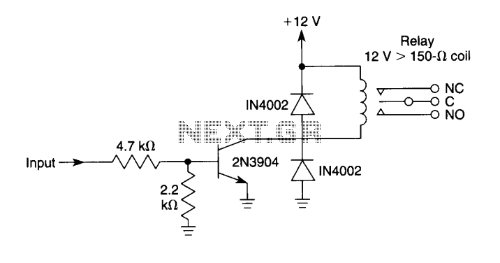
This circuit can be used to drive a 12V relay with a triggering signal of 5V. It incorporates two 1N4002 diodes, one 2N3904 transistor, and two resistors. By altering the resistor values, the input triggering voltage can be modified. The...
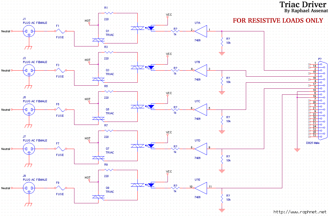
Controlling room lighting using a computer. Triacs and opto-couplers have been purchased for this purpose. A schematic was drawn and a prototype was built, which functioned correctly. Although not visible in the pictures, there is a cable extending from...