
Simple Relay Driver

The circuit described is a basic relay driver configuration that enables the control of a 12V relay using a lower voltage signal, specifically 5V. The primary components include two 1N4002 diodes, which serve crucial roles in protecting the circuit from voltage spikes and ensuring proper current flow. The 2N3904 transistor acts as a switch, allowing the relay to be activated by the 5V triggering signal.
In this configuration, the input signal is applied to the base of the 2N3904 transistor through one of the resistors. This resistor is essential for limiting the base current to a safe level, thus preventing damage to the transistor. The second resistor is typically connected in a way to set the desired triggering voltage threshold, which can be adjusted by changing its value. This flexibility allows for customization based on specific application requirements.
When the 5V triggering signal is applied to the base of the transistor, it enters saturation, allowing a larger current to flow from the collector to the emitter. This current is sufficient to energize the relay coil, closing the relay contacts and enabling control of higher voltage circuits.
The inclusion of the two 1N4002 diodes is important for flyback protection. When the relay is de-energized, the collapsing magnetic field can generate a high voltage spike. The diodes are placed across the relay coil to safely redirect this spike, preventing damage to the transistor and other components in the circuit.
Overall, this relay driver circuit is a simple yet effective solution for interfacing low voltage control signals with higher voltage loads, making it suitable for a variety of applications in automation, control systems, and electronic projects.You can use that circuit to drive a relay of 12 V with a trigering signal of 5V. It uses 2 diodes 1N4002, 1 transistor 2N3904 and two resistors. By changing the resistors value you can change the input triggering voltage.
Related Circuits
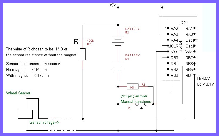
The printed circuit board (PCB) designed is large and provides ample space for modifications and additional components. However, to achieve the goal of integrating it into a real bicycle, its size presents challenges. Earlier discussions highlighted the importance of...
This is a basic Buzzer driver circuit with resonance frequency approximately 5 kHz, 85 dBA. It operates on 3 to 28 V DC at 6 mA. The basic buzzer driver circuit is designed to generate an audible tone by driving...
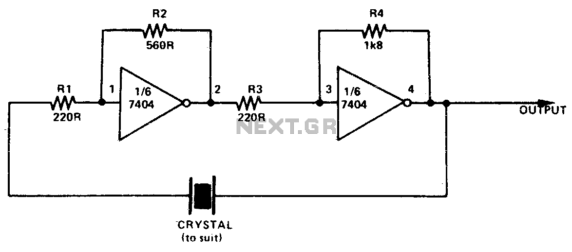
This simple and inexpensive crystal oscillator consists of one-third of a 7404 IC, four resistors, and a crystal. The inverters are biased into their linear regions by resistors R1 to R4, while the crystal provides the necessary feedback. Oscillation...
This is a simple circuit which I built to one of my audio amplifier projects to control the speaker output relay. The purpose of this circuit is to control the relay which turns on the speaker output relay in...
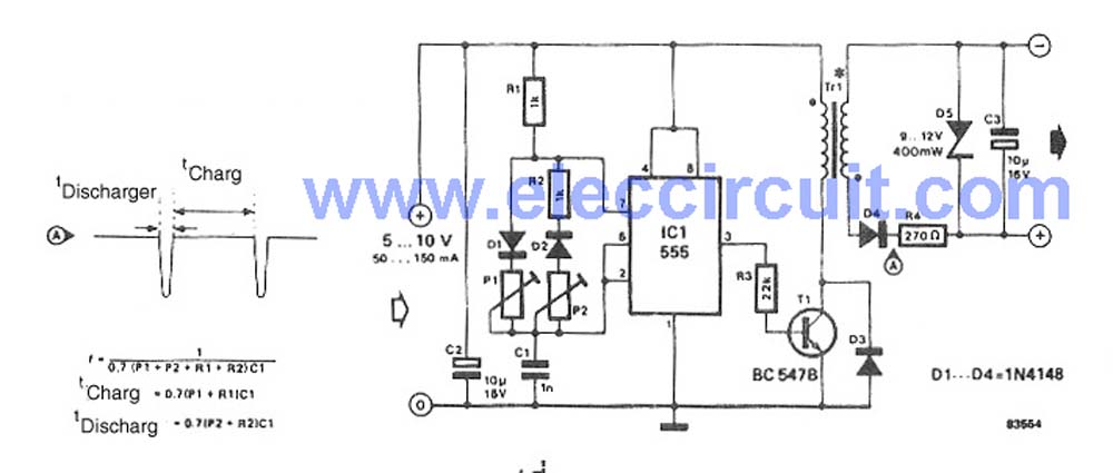
This circuit is a simple DC to DC converter designed for digital circuits. It operates with a supply voltage of 5V and provides an output voltage that steps up to a maximum of 10V-12V DC. The circuit utilizes an...
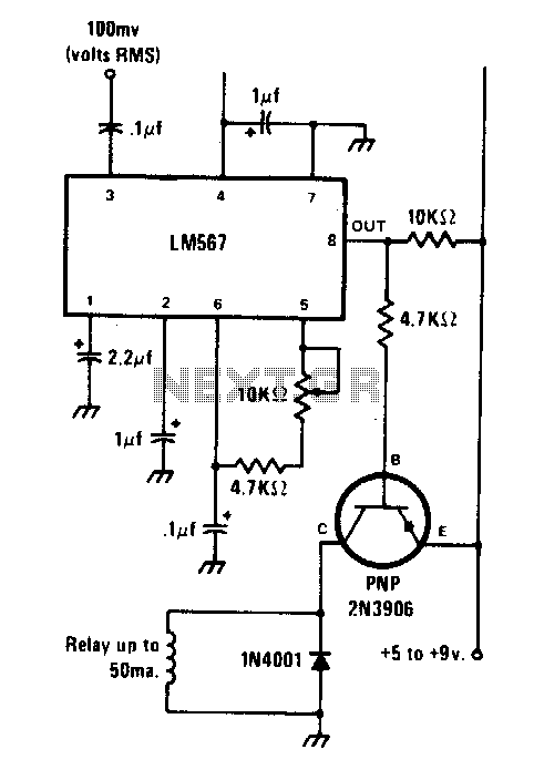
The circuit is designed using the LM567 tone decoder integrated circuit (IC), which operates with an input signal of approximately 100 millivolts at its designated frequency. The frequency can be adjusted using a 10 kΩ variable resistor, allowing it...