
Remote Alarm For Smoke Detector

This alarm circuit is engineered to ensure the safety of a shed environment, specifically designed for dog kennels. The system is integrated with a mains-powered smoke detector, which serves as the primary sensor for smoke detection within the shed. The circuit provides complete electrical isolation, which is crucial for preventing any interference from other electrical devices within the shed, thereby ensuring reliable operation of the smoke detector.
The circuit typically includes a power supply section that converts mains voltage to a lower, safe operating voltage for the alarm system. This section may utilize a transformer or a switch-mode power supply for efficiency.
The smoke detector is connected to the alarm circuit through an isolation mechanism, such as an opto-isolator, which ensures that any potential faults do not affect the mains power supply. When smoke is detected, the smoke detector sends a signal to the alarm circuit, triggering an audible alarm or visual indicator, such as a flashing LED.
Additional features may include a reset mechanism, allowing the user to silence the alarm after the smoke has cleared, and a test button to regularly check the functionality of the smoke detector and alarm system. The circuit may also incorporate a battery backup to maintain operation during power outages, ensuring continuous monitoring.
Overall, this alarm circuit is a critical component in maintaining safety within the shed, providing peace of mind to the owners of the dog kennels by ensuring that any smoke is detected promptly.This alarm circuit was designed to monitor a mains-powered smoke detector located in a shed (which is used to house dog kennels). It provides complete iso.. 🔗 External reference
Related Circuits
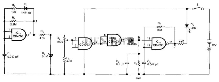
The low-voltage battery detector employs a CD4093 Schmitt trigger alongside a capacitor functioning as a 1-bit dynamic RAM. The circuit is designed to conserve power through a periodic testing method. Components IC1A, CI, R1, R2, and D1 produce a...
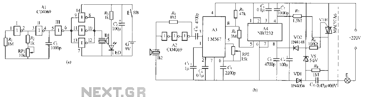
Remote control dimmer lights consist of two parts: an ultrasonic transmitter and an ultrasonic remote control dimmer receiver. The ultrasonic wave transmitter circuit is detailed in A 229 (a). It includes components such as R, R., RP1, and C,...
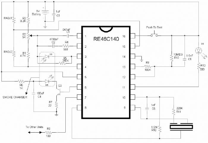
The RE46C140 circuit can be used to design a simple smoke detector alarm with minimal external electronic components. The RE46C140 IC is a low-power CMOS photoelectric smoke detector IC that provides all necessary features for a photoelectric smoke detector...
A circuit designed to extract and measure the modulated carrier of an infrared remote control. The circuit does not physically separate control pulses from modulation; instead, it amplifies the entire received signal, allowing the waveform to be ideally displayed...
This is a straightforward liquid detector that utilizes a relay to activate an evacuation valve. It can be employed for water or any conductive liquid. The liquid detector circuit operates by leveraging the conductivity of liquids to trigger a relay....

When the receiver is tuned to a medium wave radio station, feedback howl caused by the transmitter may occur when the coil and radio are positioned above or near a metal object. The search head is constructed from a...