
IR Remote Control Modulation Detector

The circuit operates effectively by leveraging the characteristics of infrared signals and the components involved. The TIL100 photodiode serves as the primary detector, responding to infrared light emitted by the remote control. The reverse biasing through a 22 kΩ resistor ensures that the photodiode operates in its optimal range, allowing for accurate detection of the modulated signal. The 10 nF capacitor plays a crucial role in coupling the signal to the first BC549C amplifier stage while blocking any direct current components that could interfere with the measurement.
The BC549C transistors are selected for their high current gain, which amplifies the small signals from the photodiode into a more substantial voltage waveform. The medium load resistor connected to the collector of the transistor further enhances the output signal, making it suitable for visualization on an oscilloscope.
The Class D amplifier configuration at the final stage is particularly advantageous, as it allows for the processing of the modulated signal without introducing additional biasing components, thus maintaining the integrity of the waveform. The output transistor effectively converts the sinusoidal waveform into a square wave, enabling easier measurement of the period with a frequency counter.
Overall, this circuit provides a robust solution for extracting and measuring the modulated carrier of infrared remote controls, making it a valuable tool for analyzing and understanding the operation of such devices.A circuit to extract and measure the modulated carrier of an Infra Red remote control. Note that the circuit does not physically separate control pulses from modulation, but amplifies the completereceived signal allowing the waveform to be displayed ideally on an oscilloscope or a frequency counter. Modulation frequencies between 1kHz and several MHz may be measured. All remote controls employing Infra Red technology use digital control signals that are modulated with a higher frequency carrier wave. The carrier wave, which is invisible to the human eye is commonly modulated between 36 and 38KHz. However, some equipment i. e. Satellite decoders may use even higher modulating frequencies. The digital control signals are relatively slow compared to the carrier frequency, typically 100 to 200 bps (bits per second).
The control pulses are sent in serial format and turn the carrier on and off. Fortunately, the control pulses of a typical remote control are long, compared to the faster modulated IR carrier wave. This very fact allows at least a few complete waveforms to be captured and measured, either on an oscilloscope or with a digital counter.
As the carrier is continually being modulated, the waveform will need to be displayed with a digital counter has a variable trigger or with an oscilloscopes manual trigger control. Light interference from nearby fluorescent light sources may also interfere with the signal, so, for this reason, I recommend to place the remote control within a few inches of the photodiode.
The detector is an IR photodiode, type TIL100. This is reverse biased via the 22k resistor and produces small changes in current when subjected to light in the IR spectrum. Ambient or steady light will produce a constant current through the photo diode, a remote control produces an alternating waveform.
The input signal is capacitively coupled to the first BC549C amplifier stage via a 10n capacitor. The capacitor will stop ambient light from passing, but not changes in light intensity. A signal of a few microamps can be passed from the photo diode into the amplifier. The high current gain of a BC549C and a medium load resistor will produce a voltage waveform that may be suitably displayed on an oscilloscope at this point. The magnitude will vary with the proximity from remote control to photo diode and also with type of remote control, hence an accurate reading is not possible.
For anyone with an oscilloscope set the volts/division control to maximum and work backwards to minimum sensitivity. The lower sensitivity of a frequency counter requires the signal to be processed further. To remove the previous amplifiers DC bias voltage, but allow only a strong modulated carrier wave to pass the last stage operates in Class D mode.
In Class D amplifiers, there are no bias components, the signal from the previous stage is used as the bias source. Therefore there will be no signal output at the collector of the rightmost BC549C under quiescent conditions, but only with a strong IR signal ( in close proximity to the photo diode).
The output transistor will be on when a positive peak arrives, and off for a negative peak. This crude method has also turned the original sinusoidal waveform into a digital one, there will be some phase shift from input to output, but the period of the waveform can still be measured. The signal can be buffered even further, if needed, the black triangle represents one gate of a CMOS 4050 buffer.
As control pulses are combined with the carrier, a frequency meter or counter is best set to measure the period of the wave, rather than the frequency. As frequency is the reciprocal of periodic time, divide 1 by the reading on the meter or counter. My own Maplin frequency counter, is shown below, displaying the result from an Aiwa Video remote control.
As can be seen (use a right click and choose your internet browsers view image) the periodic waveform is 26. 11us. This equates to 1/26. 11u = 0. 0382 Mhz or 38. 2KHz in the case of this Aiwa remote control. 🔗 External reference
Related Circuits
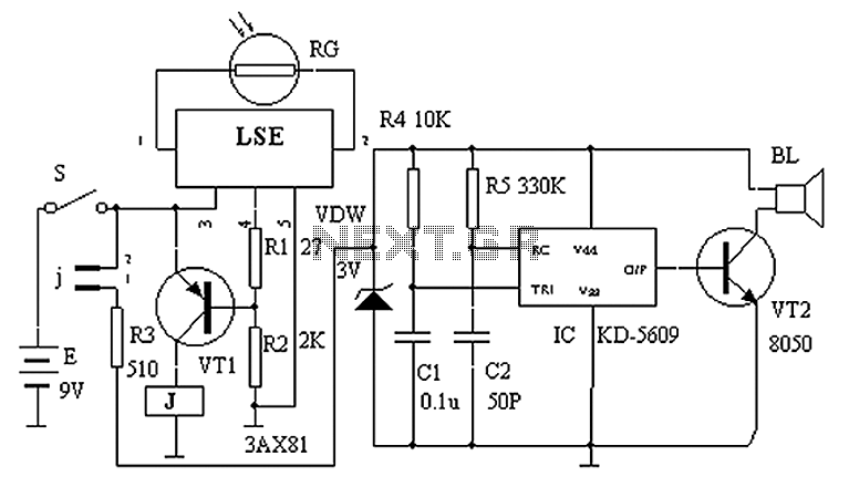
The circuit principle is illustrated in the accompanying figure. When the night light shines on the photosensitive resistor RG, it exhibits a high resistance (significantly greater than 50K). As a result, the output of the LSE pin is low,...
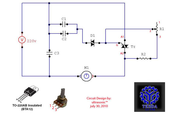
This circuit functions as a motor controller, allowing for easy control and variation of the RPM and phase of an AC motor. The power source is directly 220VAC, and it can handle a load of approximately 1 horsepower AC...
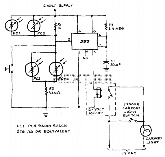
A 555 timer integrated circuit (IC) functions in one-shot mode, triggered by light exposure to photoresistors. These photoresistors typically exhibit a resistance in the range of several megohms, which decreases to several hundred ohms under light conditions, allowing current...
The schematic presented is a circuit designed for monitoring plant watering, also known as a dry soil detector. Indoor plants, whether in homes or offices, require more attention compared to outdoor plants. Due to busy schedules, it is common...
This circuit is designed for precise measurement of temperature in degrees Celsius. It features a transmitter section that converts the output voltage from the temperature sensor, which is proportional to the measured temperature, into a frequency signal. This frequency...
The project involves controlling a single-phase AC induction motor using two IGBTs. One IGBT is designated for switching the PWM signal to the motor, with a fixed PWM frequency of 16 kHz, while the second IGBT is employed for...