
Remote control for lamp or appliance

The circuit design employs a small 6-volt filament transformer, which serves as the primary power source for the triac control mechanism. The transformer’s primary winding is connected to a 120-volt AC supply, while the secondary winding is connected to a switch (S1) that controls the load. The triac is a semiconductor device that can control high voltages and currents, allowing for efficient management of the load.
In the quiescent state, with switch S1 open, the circuit experiences a magnetizing current that flows through the primary winding of the transformer. This current, although small, has the potential to unintentionally trigger the triac. To mitigate this risk, a shunting resistor (R1) is incorporated into the circuit. The value of R1 is critical; it must be set to the maximum resistance that prevents the triac from triggering while S1 is in the open position. This ensures that the triac remains off until the switch is intentionally closed.
Upon closing switch S1, the secondary winding of the transformer is effectively shorted, resulting in a significant increase in current flowing through the primary winding. This surge in current is sufficient to trigger the triac, switching it into a conducting state. As the triac turns on, it allows current to flow to the load, thereby energizing it. The triac remains in this conducting state as long as there is sufficient current flowing through it.
A critical feature of this design is that once the triac is triggered and begins conducting, it effectively interrupts the magnetizing current from the transformer’s primary winding. This self-regulating mechanism prevents the transformer from overheating or sustaining damage due to continuous current flow. The circuit thus provides a reliable means of controlling a load using a low-voltage control signal while protecting the transformer from potential failure modes.
Overall, this circuit exemplifies effective use of a triac for load control, employing a transformer and a strategically placed resistor to manage triggering conditions, ensuring safe and reliable operation.The circuit uses the primary current of a small 6 volt filament transformer to actuate a triac and energize the load. When switch Si, in the six-volt secondary, of the transformer is open, a small "magnetizing" current flows through the primary winding.
This magnetizing current may be large enough to trigger the triac. Therefore, a shunting resistor, Rl, is required to prevent such triggering. Rl, is adjusted for the highest resistance that will not cause theitriac to trigger with SI open When single-pole remote switch, SI, closes, the secondary of the transformer is shorted and a high current flows through the 120-volt primary. This triggers the triac and energizes the load. When the triac conducts, current through the primary stops and thus prevents burning out the transformer.
Related Circuits
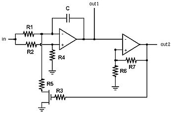
A voltage-controlled oscillator (VCO) is an electronic oscillator designed to control its oscillation frequency through a voltage input. The oscillation frequency is varied by the applied DC voltage, and modulating signals can also be introduced to the VCO for...
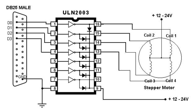
This article outlines the process of connecting a stepper motor to a computer's parallel port and writing code to control it using the scroll wheel of a mouse. For those unfamiliar with stepper motors, this project offers an engaging...
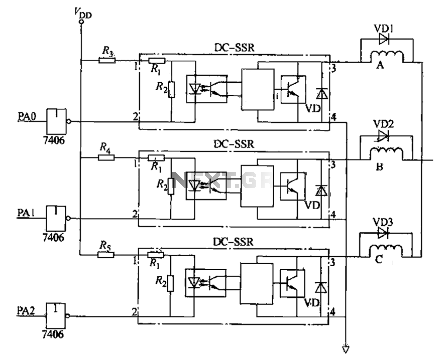
The figure illustrates that the DC Solid State Relay (SSR) in the input stage functions as an opto-isolator. When the switch output is high, the driver circuit inverts this signal to low. This process involves a light-emitting diode (LED)...

This project entitled Remote Control Through Internet allows us to monitor, control and automate our home from remote locations. In existing system home automation and security are separate systems working independently. Also in existing system if any one of...
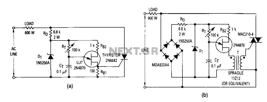
The most elementary application is a half-wave control circuit. The thyristor is acting both as a power control device and as a rectifier, providing variable power to the load during the positive half cycle and no power to the...
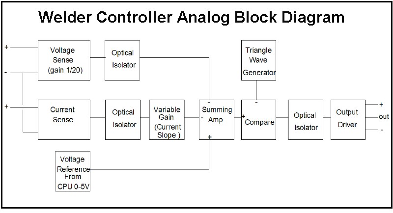
The first board is digitally controlled, while the actual welding current is analog. This design enables real-time operation without requiring the CPU to process the voltage or current. A block diagram illustrates its function: it operates as a switching...