
Computer Controlled Stepper Motor

A stepper motor is a type of DC motor that divides a full rotation into a large number of steps, allowing for precise control over angular position. This project utilizes a unipolar stepper motor, which features five wires and is characterized by its straightforward control scheme. The ULN2003 IC serves as a driver for the stepper motor, enabling it to be controlled by signals from the parallel port. The driver circuit will typically consist of the ULN2003 connected to the stepper motor terminals, with the input pins of the ULN2003 linked to the parallel port pins.
The parallel port, specifically the DB-25 connector, will be wired to the driver circuit to facilitate communication. The connection involves mapping the parallel port pins to the appropriate input pins of the ULN2003. It is essential to ensure that the wiring is correct to prevent damage to the components. A multimeter can be used to verify connections before applying power.
For software control, a programming environment that can interface with the parallel port will be required. The code will be designed to interpret scroll wheel movements from the mouse and convert those inputs into stepper motor control commands, allowing for smooth operation and precise positioning.
Safety precautions should be taken during the project, particularly concerning the power supply to the motor and the connections to the parallel port. Following the outlined steps and ensuring proper connections will yield a functional stepper motor control system that can be used for various applications, enhancing the understanding of motor control and parallel port communication.In this article, we will connect a stepper motor to our computer`s parallel port, and then we will write some code to control it with the scroll wheel on a mouse ( video ). If you have never worked with stepper motors, you will surely have a lot of fun with this project. With stepper motors, you can build things such as robots, automatic fish feed er, or even a computerized etch-a-sketch ! I`ll start off by discussing the basics of parallel ports and stepper motors. Then, we will build the driver circuit required for connecting a stepper motor to a parallel port. In the final section, we will learn how to communicate with parallel ports and how stepper motors are controlled. Hardware: A 5-wire unipolar stepper motor (these could also be salvaged from old 5 " floppy disk drives), ULN2003 IC (stepper motor driver), wire, stripboard (or a solderless breadboard ), solder and DB-25 Male connector (buy these two if you can solder.
Soldering is not necessary for doing this project, but it will ensure that your connections are secure), DB25 (female/male) parallel port cable, a multimeter, a power adapter (with voltage rating depending on your motor`s requirements) WARNING: Before we begin, I would warn you that the PC parallel port can be damaged quite easily if you make incorrect connections. If the parallel port is integrated to the motherboard, repairing a damaged parallel port may be expensive, and in many cases, it is cheaper to replace the whole motherboard than to repair that port.
Your safest bet is to buy an inexpensive I/O card which has a parallel port and use it for your experiment. If you manage to damage the parallel port on that card, replacing it will be easy and inexpensive. Don`t let that warning worry you too much, because there is a lot of fun to be had with these types of projects.
Find yourself an `antique` PC, if you can, or just buy an I/O card which has a parallel port. A parallel port is a socket found in personal computers for interfacing with various peripherals such as printers, scanners and even some webcams. On many computers, particularly laptops, the parallel port is omitted for cost savings, and is considered to be a legacy port.
However, in laptops, access to the parallel port is still commonly available through docking stations. Here`s a picture of a DB-25 parallel printer port on the back of a laptop. When a PC sends data to a printer or other device using a parallel port, it sends 8 bit of data (1 byte) at a time.
These 8 bits are transmitted parallel to each other, as opposed to the same eight bits being transmitted serially through a serial port. 🔗 External reference
Related Circuits
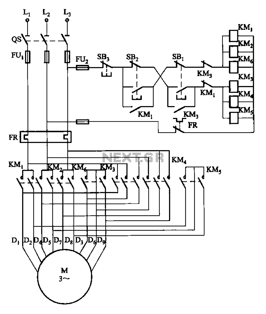
The circuit illustrated in Figure 3-107 features a low-speed operation button (SBi) and a high-speed operation button (SB2). The circuit design depicted in Figure 3-107 integrates two operational modes controlled by distinct buttons: SBi for low-speed operation and SB2 for...
Even though the power was off, there was AC present at the handle plug, and a short circuit occurred. Upon disassembly, a blown transistor was discovered. An attempt was made to fix the issue, but after one month and...
The modification of a basic speed control circuit for small DC permanent-magnet motors implements a maximum current limit during normal operating conditions and a reduced current limit during stall conditions. This design aims to limit the dissipation of series...
A servo motor employs a servo mechanism, which is a closed-loop system that utilizes position feedback to accurately control the angular position of its shaft. Stepper motors, which operate as an open-loop system, can also achieve precise angular control,...
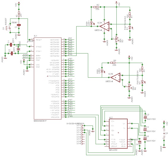
Use microcontrollers to establish serial communication between the AVR-006 kit and a computer. This project utilizes the AVR-006 microcontroller from Circuits-Home. Before developing the program, it is essential to understand the hardware specifications. An example program (in C) for...
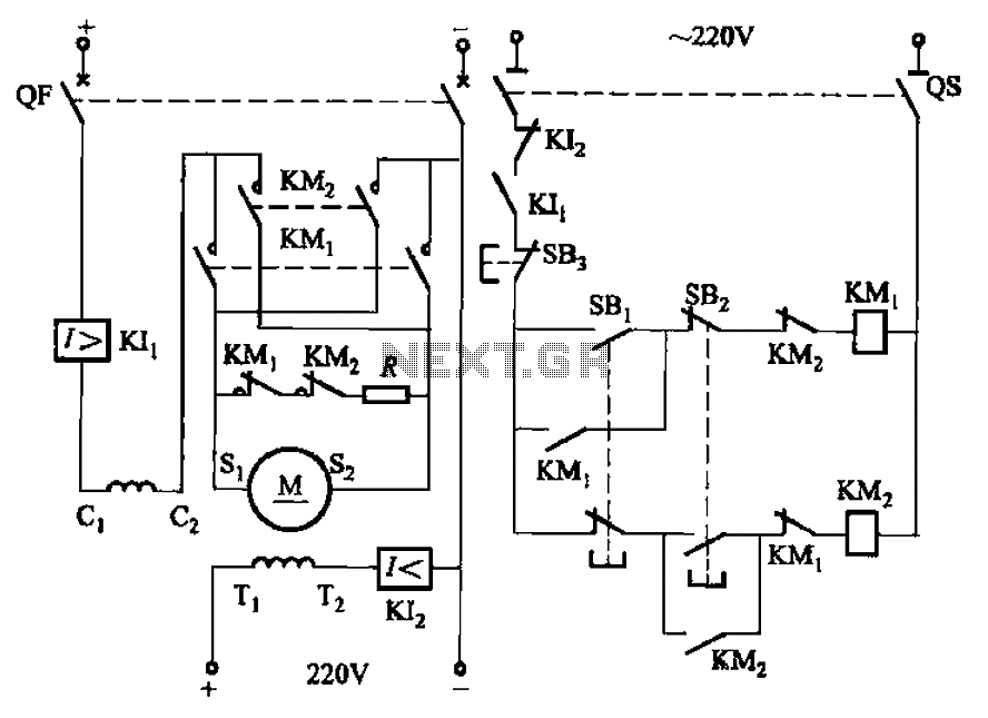
The circuit depicted in Figure 3-194 features a re-excitation type DC motor with six terminals: S1 and S2 for the armature windings; C1 and C2 for the series excitation (field) windings; and T1 and T2 for the shunt (field)...