
Remote Control Tester Circuit using Infra red sensor IC TSOP 1738

The remote control tester circuit utilizes the TSOP1738 infrared sensor, which is designed to receive modulated infrared signals from remote controls. The circuit operates by connecting the TSOP1738 to a power supply, typically 5V, and interfacing it with an LED indicator.
When the infrared sensor detects a signal from a remote control, it outputs a low logic level (0V) to the connected LED. This causes the LED to illuminate, effectively signaling that the remote control is operational. The circuit is straightforward, consisting of minimal components: the TSOP1738, an LED, a current-limiting resistor for the LED, and a power source.
The schematic diagram illustrates the connections between these components. The TSOP1738 has three pins: Vcc (power), GND (ground), and OUT (output). The Vcc pin is connected to the positive terminal of the power supply, while the GND pin is connected to the negative terminal. The OUT pin connects to the anode of the LED through a current-limiting resistor, with the cathode of the LED connected to ground.
This configuration ensures that the LED will light up only when the TSOP1738 detects an infrared signal, providing a simple yet effective means to test the functionality of various remote controls. The circuit can be assembled on a breadboard for prototyping or soldered onto a PCB for a more permanent solution.A simple remote control tester circuit with diagram and schematic using infra red sensor IC TSOP1738. An LED will blink when IR waves falls on it which indicates remote control functioning.. 🔗 External reference
Related Circuits
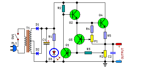
This circuit is not entirely new, but it is straightforward, dependable, robust, and short-proof. It offers variable voltage up to 24V and adjustable current limiting up to 2A. Customization to meet specific requirements is possible, as detailed in the...
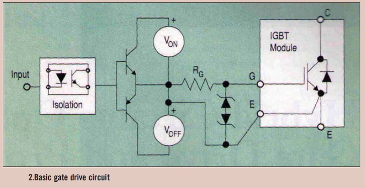
High power IGBT modules utilize hybrid integrated circuit (IC) gate drives that incorporate protection circuits, which implement desaturation detection or real-time control. High power Insulated Gate Bipolar Transistor (IGBT) modules are essential components in various high-efficiency power conversion applications, such...

The ultrasonic sensor controls and displays information through a buzzer or visual interface, alerting the driver to nearby obstacles using auditory signals or an intuitive display. This system alleviates issues related to stopping, reversing, and maneuvering around the vehicle,...
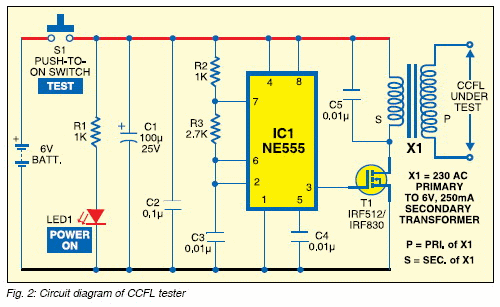
The CCFL tube is powered by a small electronic inverter circuit (CCFL inverter) that illuminates the screen electronically. This inverter circuit accepts a low-level DC input voltage and provides a high-level AC output to operate the backlight CCFL tube(s)....
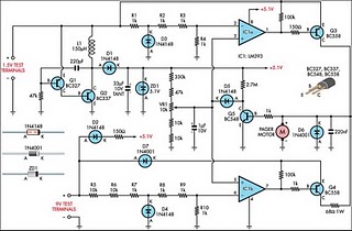
Improved Vibrating Battery Tester. This circuit is based on the LM393 integrated circuit. Features include the ability to test AAA, AA, C, and D cells. The Improved Vibrating Battery Tester utilizes the LM393, a dual comparator IC, to accurately assess...
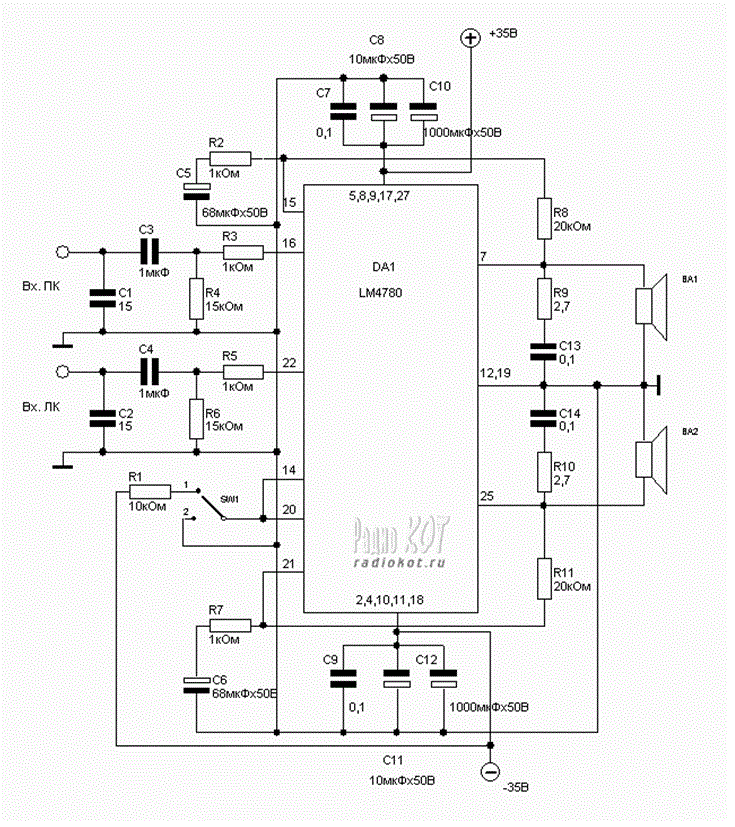
Explore the power amplifier integrated circuit from National Semiconductor, the LM4780. What is noteworthy about this component is its very low harmonic distortion. Typically, manufacturers specify the maximum power of their products with a harmonic content of around 10%....