
Ultrasonic sensors apply to parking sensor system

The ultrasonic parking sensor system is comprised of several key components that work together to enhance vehicle safety during low-speed maneuvers. The primary component is the ultrasonic transducer, which emits high-frequency sound waves that are inaudible to humans. These waves travel through the air and bounce off nearby obstacles, such as other vehicles, pedestrians, or stationary objects.
The sensor module is designed to continuously emit these ultrasonic pulses at regular intervals. As the sound waves encounter an object, they are reflected back to the sensor. The time delay between the emission of the pulse and the reception of the echo is critical for distance measurement. The system calculates this distance using the speed of sound in air, which is approximately 343 meters per second at room temperature.
An integrated microcontroller processes the received signals. It converts the time delay into a distance measurement and compares this distance to predefined thresholds to determine if an object is within a potentially hazardous range. If an object is detected within this range, the microcontroller activates an alert mechanism, which can be either an audible buzzer or a visual display on the vehicle's dashboard.
The audible alert typically consists of a series of beeps that increase in frequency as the vehicle approaches an obstacle, providing the driver with real-time feedback about proximity. The visual display can take the form of LED indicators that illuminate progressively or a graphical representation on a screen, showing the distance to the nearest obstacle.
In addition to its primary function of obstacle detection, the ultrasonic sensor system can be integrated with other vehicle systems, such as rear-view cameras or parking assist technologies, to provide a comprehensive safety solution. This integration enhances the driver's situational awareness, reduces the likelihood of accidents during parking or reversing, and ultimately contributes to safer driving practices.
Proper installation and calibration of the ultrasonic sensors are critical for optimal performance. The sensors should be mounted at the appropriate height and angle to ensure accurate detection of obstacles. Environmental factors, such as weather conditions and the presence of dirt or debris on the sensor surface, can also affect performance, necessitating regular maintenance checks to ensure reliability.By the ultrasonic sensor, control and display (or buzzer) and local composition, it can tell the driver his around obstacles by voice or a more intuitive display case. Relieve the driver stop, reverse and start to visit around the vehicle caused by problems, and to assist the driver to clean the line of sight angle and sight ambiguous death of the
shortcomings of progressive drive insurance. Ultrasonic parking sensor works by ultrasonic pulse from the sensor (transducer) to issue, reflected by the surface acoustic wave sensor to receive the same after the conversion into electrical signals, then, through the time of transmitting and receiving sound waves to calculate the distance from the sensor to the measured object. When close to a safe distance when reversing, it can tell the driver his around obstacles by voice or a more intuitive display case.
🔗 External reference
Related Circuits

This design circuit is for a temperature sensor that utilizes an LM335 integrated circuit (IC) to convert ambient temperature into an equivalent output voltage. The output voltage of the LM335 increases by approximately 10 mV for every 1 degree...
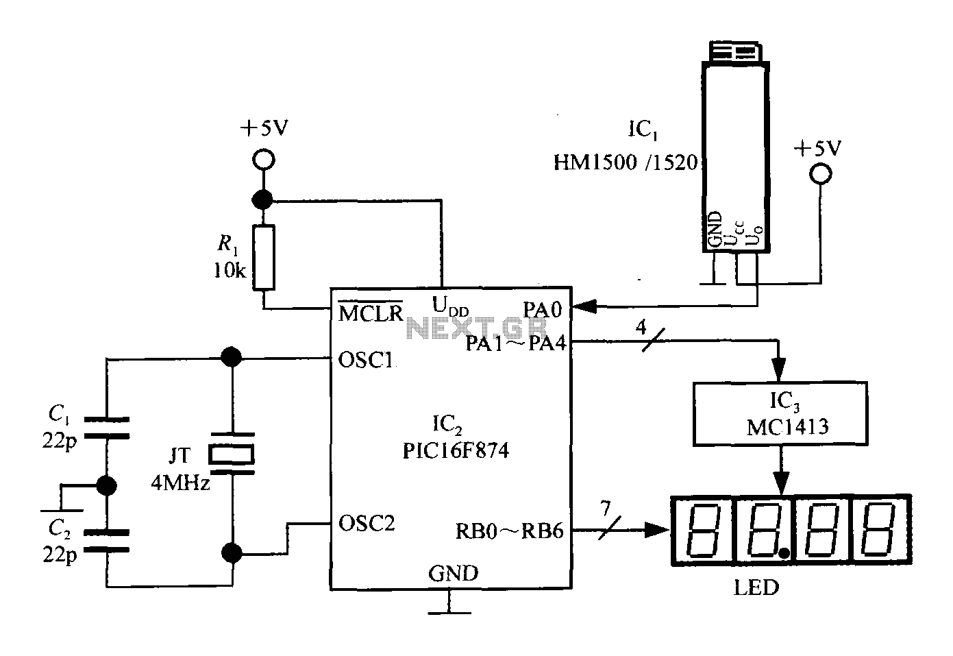
An intelligent humidity meter circuit utilizing the HM1500/1520 humidity sensor and a microcontroller configuration. The circuit operates on a +5V power supply and incorporates four common cathode LED digital displays. It employs three integrated circuits: IC1 is the HM1500/1520...
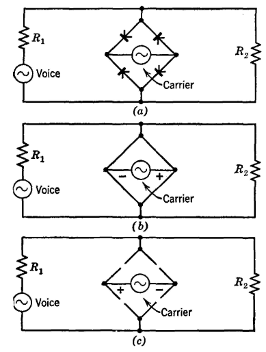
The Type C system was first installed around 1925 and has been extensively utilized since then. It incorporates the most desirable features of previously considered systems. Similar to the Type A system, the carrier signal is suppressed, minimizing the...
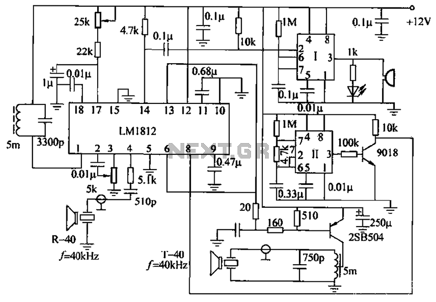
The ultrasonic anti-collision circuit is designed using the LM1812 integrated circuit, which controls both the transmission and reception functions. A distance control potentiometer allows for adjustments within a range of 2 to 3 meters. The timebase circuit is constructed...
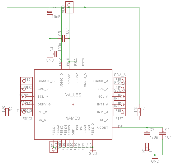
Establish communication between the microcontroller unit (MCU) and the accelerometer using either I2C or SPI protocols. It has been noted that shorting the phase-locked loop (PLL) filter input in the device does not affect the readings from the gyroscope...
This is a circuit diagram for automatic muting in audio systems utilizing the IC LB1403. The output from a pre-amplifier, such as the LA3160, LA3161, or HA1032, is connected to the base of the amplifier transistor BC548 (T1). A...