
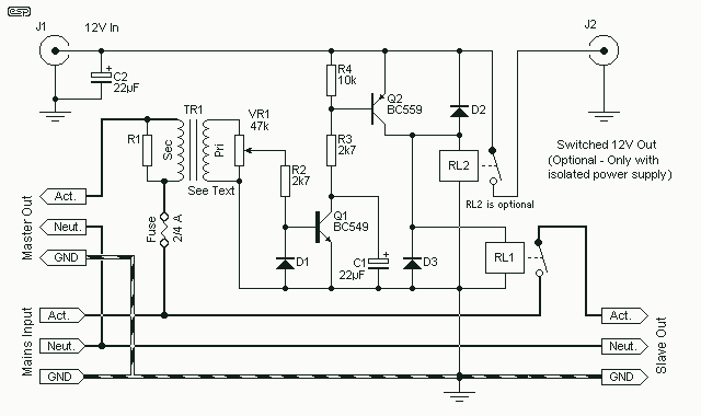
Remote Doorbell Warning Switch

The circuit comprises a solenoid-type doorbell switch, a series resistor (R1), a transistor, a lamp, and an electromechanical counter. The solenoid-type switch is the initiating component that, when pressed, allows current to flow through R1. The resistor R1 is crucial for limiting the current drawn from the doorbell, thus prolonging the lifespan of the power source. The choice of R1 is critical; it should be selected to ensure that the voltage drop across it is optimal for triggering the transistor without causing excessive power loss.
The transistor acts as a switch that controls the lamp. When the voltage across R1 reaches the specified threshold, the transistor is activated, allowing current to flow from the collector to the emitter, thereby illuminating the lamp. This provides a clear visual indication that someone is at the door, which is especially useful in environments where the doorbell sound may not be heard.
In addition to the lamp, the inclusion of an electromechanical counter serves a dual purpose. It not only tracks the number of times the doorbell is pressed but also enhances the circuit's functionality. The counter is connected in parallel with the lamp, ensuring that it operates independently while still receiving the necessary current to function correctly. This feature can be particularly useful in monitoring visitor frequency or for security purposes.
Overall, this circuit design effectively addresses the limitations of traditional doorbell systems by combining auditory and visual indicators, ensuring that the presence of visitors is communicated effectively, regardless of surrounding noise levels.This circuit will light a lamp at a remote location when the doorbell switch is pressed. This circuit should only be used with the solenoid type doorbells, the electronic type that play tunes will not work here. It is quite easy to miss the sound of a doorbell if you are watching TV, this circuit gets round the problem by providing a visual indic
ation. As an alternative, a LED could also be used. You could just parallel a lamp across the doorbell, but this would mean extra drain from the doorbell batteries or transformer. A series resistor, R1 is wired in series with the doorbell and reduces current flow, thereby increasing battery life.
The value of R1 is chosen so that about 0. 6 to 0. 7 volts is developed across it, when the doorbell switch is pressed. I used a combination of a 22 ohm resistor in parallel with a 50 ohm. The voltage drop across R1 is sufficient to switch on the transistor, the lamp in series with the collector will then illuminate. I also used an electromechanical counter in parallel with the lamp. This registered each time someone pressed the switch. 🔗 External reference
Related Circuits

Utilize the call sheet to touch the electrical threshold M, which causes the E lamp to light up. When the same interval subparagraph is triggered, the lights will automatically turn off. A voltage regulator rectifier circuit is formed using...
Switch on one unit, and everything else you need turns on automatically. This can save the tedium of turning on half a dozen different things, when one should be enough! This is another project created purely from necessity. In...
Remote controls are often needed to manage various electric devices. There are several types of remote controls available, including infrared, RF (Radio Frequency), and SMS. Basic short-range remote controls primarily utilize infrared and RF technology. A limitation of infrared...

A transmitting circuit powered by an infrared light-emitting diode emits light. The receiving circuit, shown in the figure, utilizes a transistor (3DU5) to receive the infrared light and output the received signal. The signal is sent to terminal 3...

The core of the switch controller is an Arduino Nano microcontroller, which will serve as the interface between the dashboard switches, wireless steering wheel buttons, and the vehicle's lighting, indicators, windscreen wipers, and DigiDash2 GPS stopwatch. This setup facilitates...
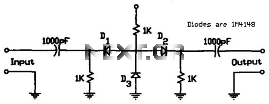
This circuit utilizes low-cost IN4148 diodes and demonstrates approximately 1.5 dB insertion loss across the frequency range of 10 to 1000 MHz with a few volts of negative bias. Under these conditions, diode D3 conducts while diodes D1 and...