
Inexpensive Vhf/Uhf Diode Rf Switch

The described circuit is a simple yet effective RF switch that leverages the characteristics of the IN4148 diodes to control signal paths based on the applied bias voltage. The use of these diodes is advantageous due to their low cost and availability, making the circuit suitable for budget-sensitive applications.
In the circuit, the insertion loss of approximately 1.5 dB indicates that the switch maintains a relatively low level of signal attenuation, which is crucial for RF applications where signal integrity is paramount. The isolation of 30 to 50 dB achieved in the negative bias state means that when one path is activated (D3 conducting), the other paths (D1 and D2) are effectively blocked, preventing signal leakage and ensuring that the output is clean and unaffected by other channels.
The switching mechanism relies on the biasing of the diodes. In the negative bias condition, D3 is forward-biased, allowing current to flow through it while cutting off D1 and D2. Conversely, applying a positive bias forward-biases D1 and D2, allowing them to conduct while D3 is turned off. This dual-state operation enables the circuit to switch between different signal paths effectively, making it versatile for various RF switching applications.
The circuit design can be further enhanced by incorporating additional components such as resistors to limit current through the diodes, capacitors for filtering, or inductors for impedance matching, depending on the specific requirements of the application. Overall, this low-cost RF switch circuit is an efficient solution for applications needing reliable signal routing with minimal insertion loss and high isolation. This circuit uses low-cost IN4148 diodes and exhibits about 1.5 dB insertion loss from 10 to 1000 MHz w ith a few volts of negative bias. D3 conducts and D1/D2 are cut off, which results in 30 to 50 dB isolation. When a few volts of positive bias are applied, Dl and D2 are biased on and D3 is cut off. This circuit should be useful in applications where a low-cost RF switch is necessary.
Related Circuits
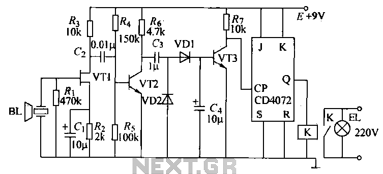
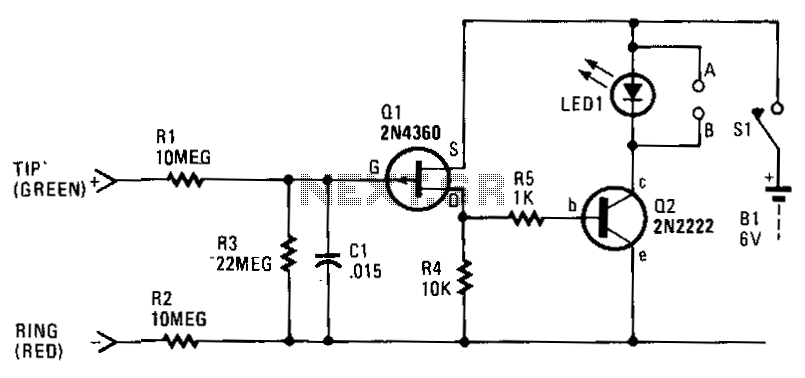
This simple circuit, as shown in the schematic diagram, activates a switch using sound. It can be utilized for various applications, such as an automatic sound-controlled disco light or a car's LED light show. The transistor Q1 amplifies the...
The T-40-16 and 555 ultrasonic transmitter circuit configuration consists of an ultrasonic transmitter T-40-16 and a 555 timer circuit. By adjusting the potentiometer RP, the oscillation frequency of the circuit can be changed. The output pulse frequency from the...
The DTMF codec stands for dual-tone multi-frequency codec. The multiple-channel infrared remote control switch circuit that incorporates the DTMF is depicted in the figure. It consists of an infrared remote control signal emitter, an infrared receiving signal amplifier, a...
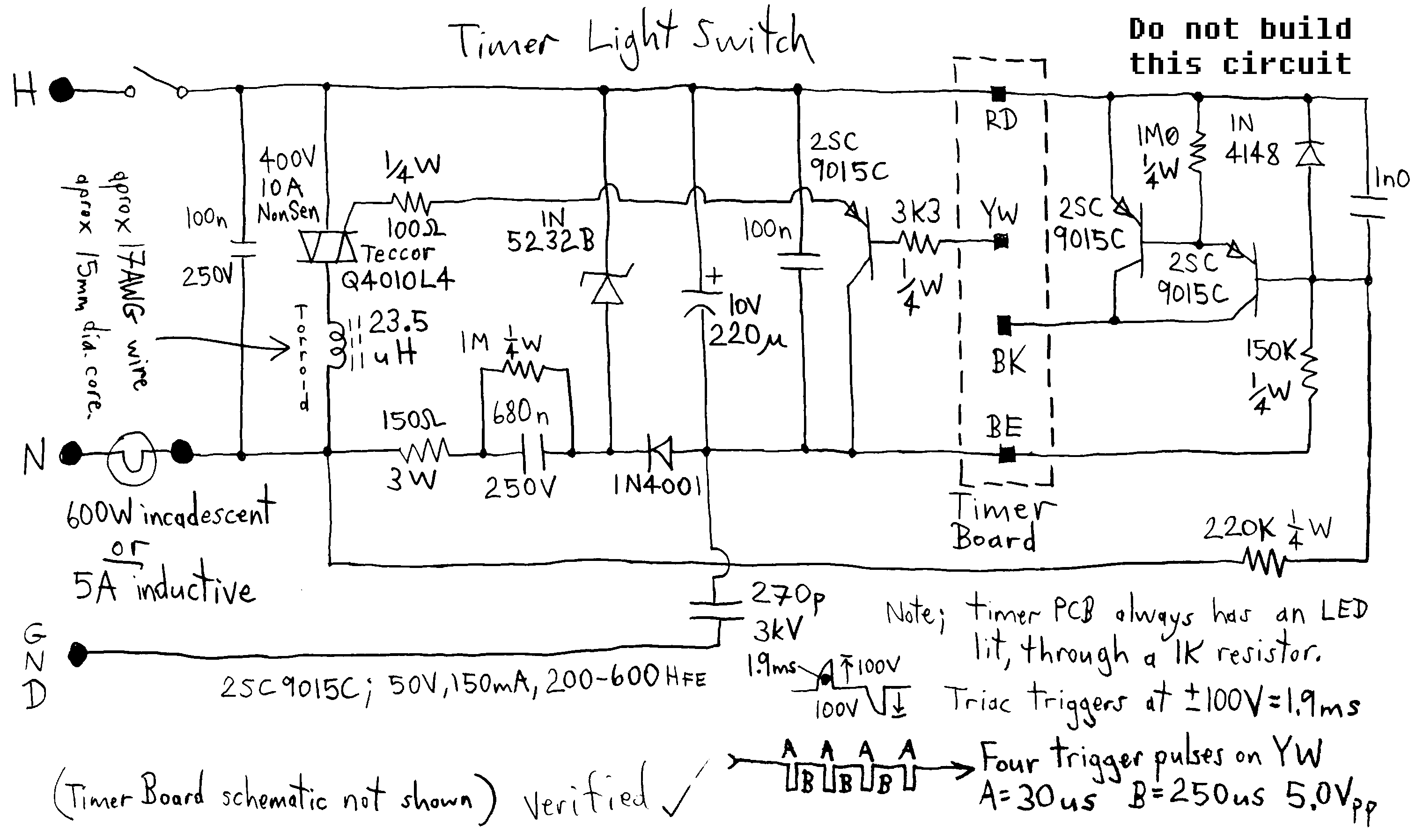
Typical circuit representative of those used in most light switch type digital timers. The timer module is normally a PIC or custom chip, and it syncs to the AC line so that a trigger pulse can be supplied at...
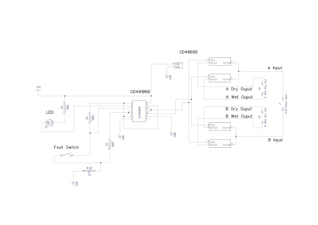
A simple audio switching circuit is experiencing issues. The circuit utilizes a CD40106 Schmitt Trigger in conjunction with a CD4066 CMOS switch to route audio signals. The circuit design incorporates a CD40106 Schmitt Trigger, which is essential for providing clean...
Each time a phone on the same line or calling number is taken off-hook, the circuit activates to control an external electronic circuit. If multiple extension telephones are connected to one phone line, the circuit serves as a busy...