
REMOTE TV VOLUME CONTROL
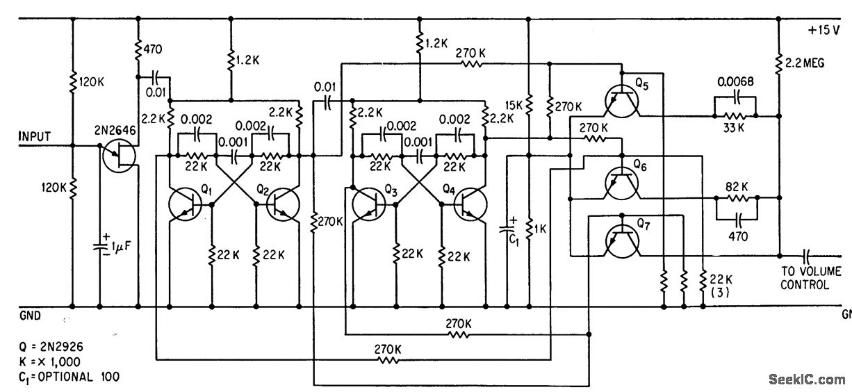
The circuit operates by utilizing ultrasonic signals emitted from a handheld transmitter. Upon detection by the microphone, these signals are converted into electrical impulses. The UJT threshold detector (2N2646) is pivotal in this process, as it identifies the incoming signal and generates a corresponding trigger pulse. This pulse is essential for the operation of the subsequent bistable dividers.
The two cascaded bistable dividers serve as a control mechanism for the volume adjustment. Each divider can be set to toggle between states, which in turn activates the transistors responsible for modulating the volume output. The transistors are strategically placed across the volume control pathway, allowing for full volume when no shunting occurs, and enabling three distinct lower volume levels when activated.
This configuration provides a versatile solution for volume control in audio applications, particularly in scenarios where remote operation is desired. The use of ultrasonic signals allows for non-invasive control, minimizing the need for physical interaction with the volume control knob. The design emphasizes efficiency and user convenience, making it suitable for various electronic devices that require adjustable sound output.Ultrasonic bursts from handheld transmitter are picked up by microphone and fed to ujt threshold detector 2N2646 that also generates trigger pulse. Two cascaded bistable dividers control three transistors shunted across volume control, to give full volume (no shunting) and three lower volume levels.
-J. H. Phelps, Transistors Instead of Relays Tune TV Volume, Electronics, 37:9, p 32-33. 🔗 External reference
Related Circuits
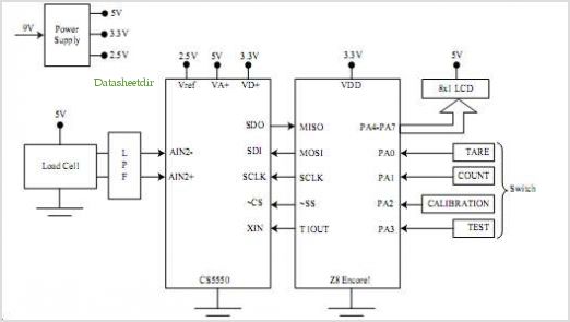
The SP6691 circuit is designed to provide a high output voltage using a lower voltage boost regulator by incorporating a charge pump circuit. This configuration can convert a standard 30V boost regulator into a 60V boost regulator if necessary....
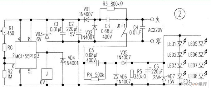
The circuit is depicted in Figure 1, while the electrical schematic diagram is presented in Figure 2. The AC voltage of 220V is reduced by components C3 and R3. The diodes VD1 and VD2 rectify the voltage, and capacitors...
Four way Traffic light controller which Has Red, Yellow and Green LEDS. It uses the AT89C2051. The four-way traffic light controller is an essential electronic system designed to manage traffic flow at intersections by controlling the operation of Red, Yellow,...
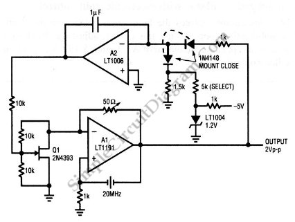
This is a quartz-stabilized oscillator circuit with electronic gain control. Replacing the common filament lamp for amplitude stabilization, this circuit uses... This circuit represents a quartz-stabilized oscillator featuring electronic gain control, which enhances the stability and precision of the output...
A challenging issue in the design of traditional stereo tone controls is achieving synchronized movement of the potentiometers. Even minor discrepancies in synchronization can lead to phase and amplitude variations between the two audio channels. Additionally, linear potentiometers are...
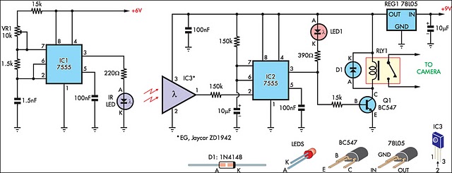
The IR detector (IC3) controls an LM 7555 CMOS timer (IC2) operating in monostable mode. When the beam is interrupted, IC2 is triggered, causing its pin 3 output to go high for approximately half a second. This action turns...