
Light control automatic energy-saving LED lights circuit

The circuit operates by first stepping down the high voltage AC input of 220V through a resistor-capacitor (RC) network consisting of C3 and R3. This reduction is crucial for protecting downstream components from high voltage. The resulting AC voltage is then passed through two diodes, VD1 and VD2, configured in a bridge rectifier arrangement. This configuration allows for the conversion of the AC voltage into pulsating DC voltage.
Following rectification, the capacitors C2 and C1 play a vital role in smoothing the pulsating DC. C2 is typically larger and serves to filter out the majority of the ripple, while C1 provides additional filtering to ensure a more stable DC output. The combined effect of these capacitors is to produce a smooth, steady voltage supply suitable for sensitive electronic components.
The voltage-regulator diode is essential for maintaining a consistent output voltage of 6V. This regulated voltage is crucial for the proper operation of the MC1455P1G, which is a timer IC used in various applications, including timing and pulse generation. The MC1455P1G requires a stable voltage to function correctly, and the regulator ensures that fluctuations in the input voltage do not affect its performance.
Additionally, the circuit includes a photosensitive resistor, which is sensitive to light levels. During the daytime, the resistance of this component decreases, allowing more current to flow through the circuit. This feature can be used in applications such as light-activated switches or automatic lighting systems, where the circuit responds to ambient light levels.
Overall, this schematic illustrates a well-designed power supply and control circuit that effectively manages high voltage AC input, converts it to a stable low voltage DC output, and incorporates a light-sensitive element for responsive operation in varying light conditions.Circuit is shown in Figure 1,electrical schematic diagram is shown in Figure 2. The voltage AC220V is reduced by C3,R3 discharges,VD1 and VD2 rectify,C2 and C1 filter and get a smooth direct current,the voltage-regulator diode stabilizes the voltage in 6V and supplys the power for MC1455P1G and photosensitive resistor.In the daytime,photosensitive resistor R.. 🔗 External reference
Related Circuits
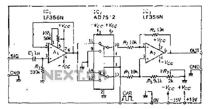
An analog switch (double loop, double-break) and a differential modulation amplifier are used in this circuit. The carrier control switch operates by switching contacts at specific times, inverting the input modulation wave. When the next carrier signal is applied...
A battery-status indicator circuit is useful for monitoring portable test equipment and similar devices. LED D1 flashes to attract the user's attention, signaling that the circuit is operational, preventing it from being left on unintentionally. The circuit produces approximately...
Touch the sensor of the alarm with your finger, and it starts beeping. It continues for a period and then stops. Touching it again will activate the beeping once more. This description outlines a basic touch-activated alarm system. The...

The circuit generates a clock that is synchronized with the pulse width of two clock pulses, producing a random pulse width that is five times the input pulse width of the clock pulse. In the flip-flop circuit, A and...
This indicator shows through a dual-LED see if a fuse is intact. The module is designed for 230 V AC. The green LED illuminates when the fuse is still good, the red lights when the fuse is broken. Perhaps...
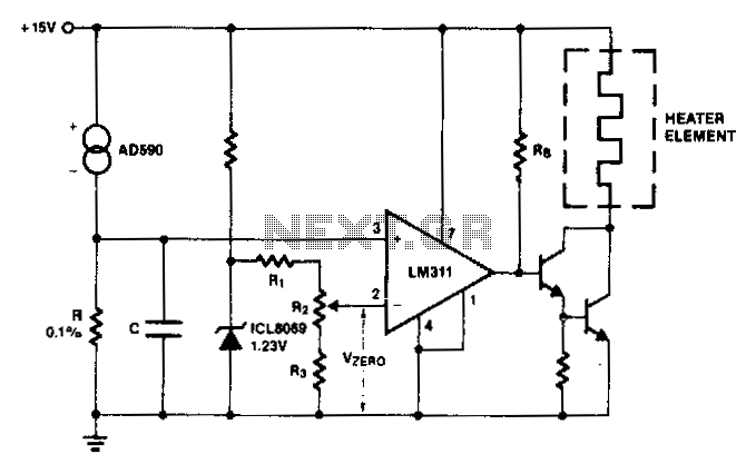
The AD590 generates a voltage that varies with temperature across resistor R, while capacitor C serves to filter out noise. To establish a zero-scale voltage, resistor R2 is adjusted. For the Celsius temperature scale, R should be set to...