
audio surround decoder circuit diagram

The circuit is designed to enhance the listening experience by providing a well-balanced stereo sound output with an emphasis on surround sound capabilities. The use of operational amplifiers (TL072) ensures low noise and high fidelity in the audio signal processing. The summation of left and right channels via IC2C allows for effective center channel output, crucial for clear dialogue and central audio cues in surround sound systems.
IC2D's role in phase manipulation is essential for creating an immersive audio experience, particularly in larger rooms where sound dispersion can affect perceived audio quality. The careful design of the rear speaker connections, ensuring that negative terminals are not grounded, allows for optimal performance in parallel configurations with the main speakers.
The integration of the MN3004 sound delay IC adds a sophisticated layer to the audio output, allowing for adjustable delays that can enhance the spatial audio effect. The synchronization provided by the MN3101 timing signal ensures that the delay effects are coherent and aligned with the original audio signal, preventing any dissonance.
The inclusion of variable capacitors for delay adjustments and filters for frequency management demonstrates a thoughtful approach to audio signal integrity. The filters are specifically tuned to eliminate unwanted noise and maintain the desired frequency response, ensuring that the rear speakers operate effectively within their designed bandwidth.
Overall, the circuit is a comprehensive solution for creating a high-quality surround sound experience, with various components working in harmony to enhance audio fidelity and spatial awareness. Each output's potentiometer allows for fine-tuning, ensuring that the system can be tailored to the specific acoustics of the environment it is installed in. The 15 V power supply is adequate for driving the necessary amplifiers, making this circuit suitable for a range of audio applications.The operation of the circuit starts up and transport the stereo surround sound signal quality information on the master volume circuit. This will drive the left channel connected to LCH Model TL072 IC1A IC1B and attached to the right channel Rch.
The outputs of these operational amplifiers serve as the input buffer for the next stages of the circu it. IC2C is responsible for the sum of the signals from left and right to power the center speaker output, while IC2D is responsible for increasing the phase difference between left and right, which is encoded in the two channels and be fed to the rear speakers. It is necessary to ensure that the negative terminals from the rear speakers is not grounded, since it will only work in parallel with the main speakers.
The output of the power unit regulated IC2D takes audio to rear speakers. This would lead to the creation of sense of separation, according to the size of the room. This will incorporate signal amplifier IC5 MN3004 sound delay that has 512 steps. From IC4 MN3101 is a timing signal, which provides synchronization of IC5 as it functions as an oscillator in the circuit. C17 variable capacitor regulates the delay in the circuit. The presence of filters in the circuit is in order to avoid the noise that occurs during the process.
These filters can be adjusted to cut the frequencies above 8 kHz and below 100 Hz, to be able to drive the rear speaker. The rear speaker is small and that their entry is encoded with a bandwidth of 100 Hz to 8 KHz. The filters are built around the IC6A / B is also an output buffer. A potentiometer is placed on each output to aid in the adjustment and regulation of speakers and amplifiers.
The energy supplied in the circuit is 15 V and each output can drive a single power amplifier. 🔗 External reference
Related Circuits
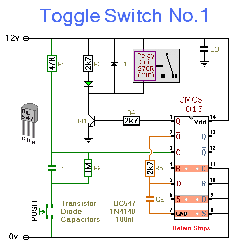
This simple circuit will energize and de-energize a relay with the push of a button. Pressing the button once will energize the relay, while pressing it a second time will de-energize the relay. The accompanying circuit provides a solid...
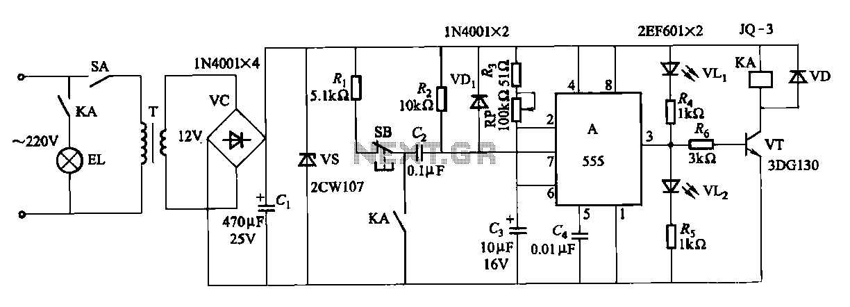
The second circuit for darkroom time exposure utilizes a 555 timer integrated circuit (IC A) for timing functions. A relay controlled by the circuit regulates the exposure light source. The exposure time can be adjusted using potentiometer RP, allowing...
T1 and T2 in the circuit form the inherent oscillator, while T3 serves as the output stage. The network consists of a high-pass filter (C3, C4, R6, and R7) and a low-pass filter. The output from this network is...
A crystal oscillator circuit is a straightforward oscillator circuit that can be easily understood through its schematic diagram. It serves as a replacement for a conventional oscillator network, which typically consists of an LC combination. This simplicity is also...
The tester provides an audible indication of the logic level of the signal presented to its input. A logic high is indicated by a high tone, a logic low is indicated by a low tone, and oscillation is indicated...
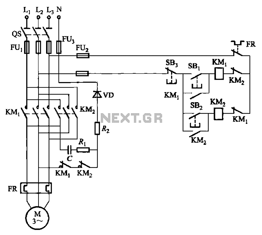
The circuit depicted in Figure 3-146 eliminates the need for a step-down transformer by utilizing the principle of energy storage through capacitor discharge for braking. It can be employed to frequently start and stop a motor with a power...