
Repeater beeper

The circuit operates by utilizing a signal from the COR (which could represent a control or output relay) to activate an integrated circuit designated as U1. This component is responsible for generating a beep-gate pulse, a short-duration pulse that serves to control the operation of an analog gate. The analog gate is formed by diodes D2 and D3, which are configured to allow the passage of a specific audio signal, in this case, a beep tone produced by another integrated circuit labeled U2.
The design ensures that when the COR signal is activated, U1 generates the necessary pulse to enable D2 and D3, allowing the beep tone from U2 to be transmitted through the circuit. This configuration is commonly used in applications requiring audible alerts or notifications, where the precise timing of the beep is crucial for user feedback or system alerts. The careful selection of components and their arrangement in the circuit plays a significant role in achieving the desired performance and reliability of the system.The signal from COR triggers U1 which produces a beep-gate pulse that enables the analog gate Consisting of D2 and D3 to pass the beep tone generated by U2.
Related Circuits
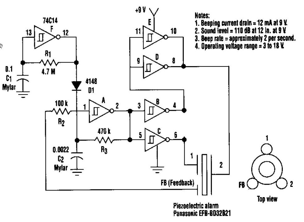
This beeper circuit generates an impressive 110dB sound level from a 9V supply. The design employs a single 74C14 (CD40106B) CMOS hex inverting Schmitt-trigger integrated circuit (IC), which must be paired with a piezoelectric device featuring a feedback terminal....
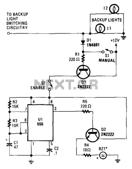
When the vehicle's backup lights are activated, or when the manual switch (SI) is closed, a small current is supplied to the base of Q1. Transistor Q1 allows current to flow through it and, if the enable switch (S2)...
For the simplest functions, such as a flashing indicator and/or beeper, a printed circuit board is not necessary. Components can be directly soldered onto the legs of the PIC microcontroller, using heat-shrinkable sleeves for insulation. Caution is advised to...
The test beeper generates a sinusoidal signal with a frequency of 1,000 Hz, which is a standard test frequency for audio amplifiers. It utilizes a Wien-Bridge oscillator configuration, also referred to as a Wien-Robinson oscillator. The frequency-determining network comprises...
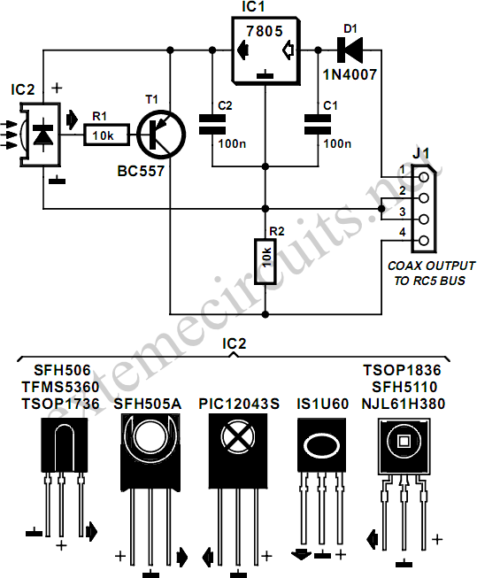
The designer of this circuit installed two waterproof loudspeakers in the bathroom and connected them to the living room stereo system using a long cable. This setup led to the desire for remote control functionality from the bathroom. Commercial...
After installation in the car (not running but in reverse with the emergency brake engaged), the system functioned well. However, when the car was started and reversed out of the garage, the beeping frequency became erratic while tapping the...