
110dB Beeper Circuit

The beeper circuit operates effectively by utilizing the properties of the 74C14 CMOS IC, which provides robust performance in generating square wave signals suitable for driving piezoelectric devices. The astable oscillator configuration allows for continuous oscillation, which is crucial for producing sound. The choice of operating frequency, specifically set to five times lower than the resonant frequency of the piezoelectric element, maximizes sound output due to resonance effects. The feedback mechanism is essential for stabilizing the oscillation frequency, ensuring that the piezoelectric device operates efficiently.
The cross-wiring of the inverter sections introduces a differential drive signal, which enhances the voltage swing across the piezoelectric element, thus increasing the sound pressure level generated. The additional astable oscillator serves a dual purpose; it can modulate the sound output at a lower frequency, providing a pulsing effect if desired. However, for applications requiring a steady tone, the modulation can be bypassed by eliminating the associated circuitry.
This circuit design showcases the versatility of CMOS technology in audio applications, particularly in generating high-decibel sound levels from a compact and efficient setup. The careful consideration of frequency, feedback mechanisms, and drive configurations contributes to the effective performance of the beeper circuit, making it suitable for various signaling applications.This beeper circuit will generate an car-splitting 110dB from 9V. The setup uses a single 74C14 (CD40106B) CMOS hex inverting Schmitt-trigger IC, which must be used with a piezoelectric device with a feedback terminal. The feedback terminal is attached to a central region on the piezoelectric wafer. When the beeper is driven at resonance, the feed back signal peaks. One inverter of the 74C14 is wired as an astable oscillator. The frequency is chosen to be 5 times lower thant the 3, 2KHz resonant frequency of the piezoelectric device. Feedback from the third pin of the beeper reinforces the correct drive frequency to ensure maximum sound output.
Four other inverter sections of the IC are wired to form two separate drivers. The output of one section is cross-wired to the input of the second section. The differential drive signal that results produces about 18Vpp when measured across the beeper. The last inverter section is wired as a second astable oscillator with a frequency of about 2 Hz. It gates the main oscillator on and off through a diode. For a continous tone, the modulation circuit can be deleted. 🔗 External reference
Related Circuits
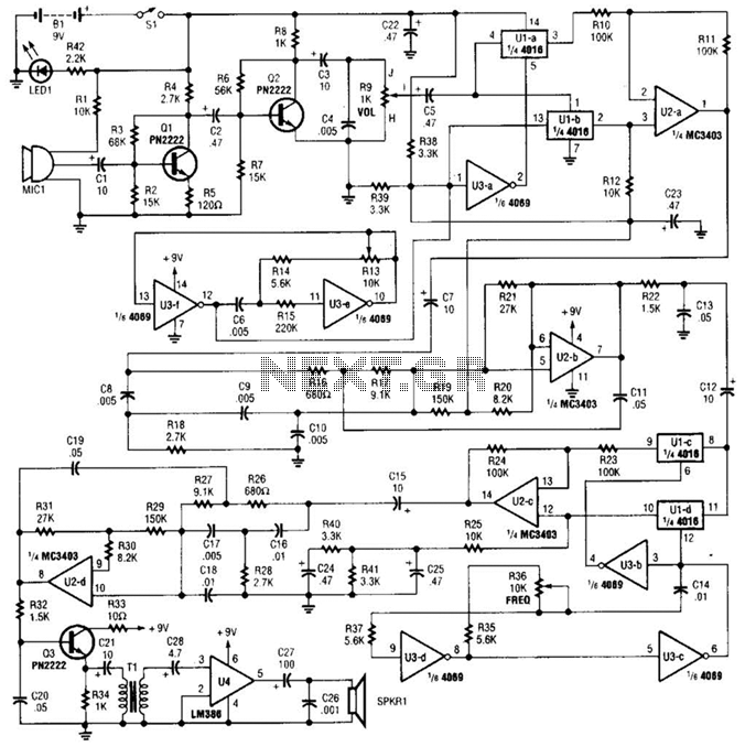
A complete schematic diagram of the voice disguiser is presented. Microphone MIC1 captures the voice signal and transmits it to an audio amplifier, which consists of Q1 and Q2, along with several supporting components. This amplifier features a low-pass...
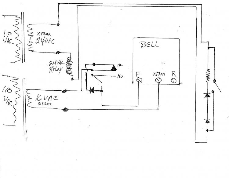
A new wired doorbell has been installed, specifically the Heath/Zenith Model #LE-65-B (Electronic). A new 16 Volt transformer was also added, along with a lighted pushbutton and a diode. Initially, all components functioned correctly, including the lighted pushbutton. However,...

Although LEDs dominate the lighting market today, a standard flashlight bulb can still be a viable light-emitting option, particularly due to its simpler configuration compared to an LED. When the AC mains supply fails, transistor T1 becomes forward-biased, allowing...
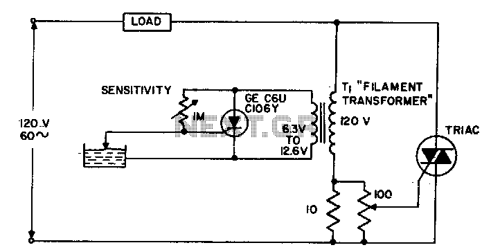
The circuit supplies power to the load until water conducts through the probe, allowing gate current to bypass from the low current SCR. This configuration provides an isolated low voltage probe to meet safety requirements. The described circuit operates as...
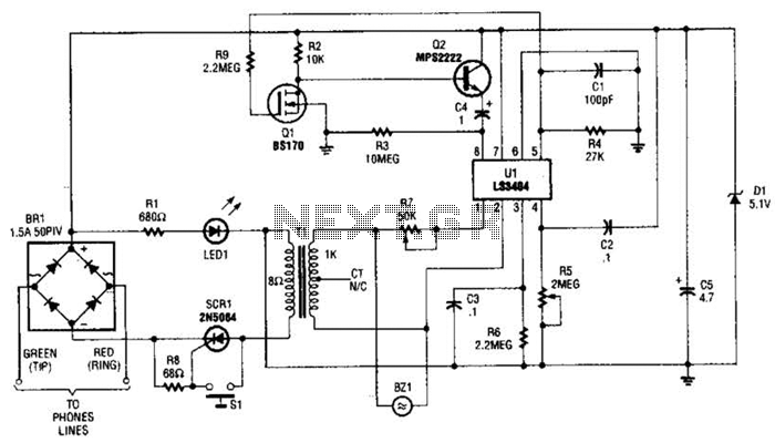
The LS3404 melody chip is activated when the hold switch (SI) is pressed, causing SCR1 to conduct and maintain the telephone line through Tl, Rl, and LED1. The voltage across Rl and LED1 is utilized to power the melody...
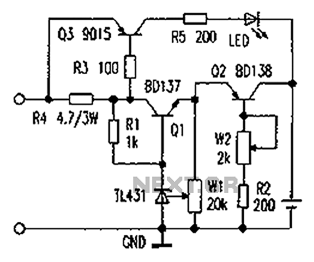
As illustrated in the figure, the lithium battery charging control board employs a constant current charging mechanism. The components Q1, R1, W1, and TL431 form a precision adjustable voltage regulator circuit. The components Q2, W2, and R2 create an...