
Repeating Interval Timer circuit

The adjustable output timer circuit utilizes a combination of resistors, capacitors, and a timer IC, such as the NE555 or similar, to achieve its functionality. The core of the circuit is the timer IC configured in astable or monostable mode, depending on the desired operation. In astable mode, the circuit continuously oscillates between high and low output states, while in monostable mode, it generates a single pulse when triggered.
To adjust the timing intervals, variable resistors (potentiometers) and capacitors are employed. The time period for the output signal can be calculated using the formula T = 1.1 * R * C for monostable mode, where T is the time period, R is the resistance in ohms, and C is the capacitance in farads. By selecting appropriate values for R and C, the output period can be finely tuned to meet specific requirements.
The circuit may also include additional components such as diodes for protection, transistors for amplifying the output signal, and relays for switching larger loads. The design should ensure that all components are rated appropriately for the voltage and current levels expected in the application.
For applications requiring longer timing intervals, it is possible to cascade multiple timer circuits or use a microcontroller to achieve greater flexibility and precision in timing. The microcontroller can provide programmable timing intervals and can be interfaced with various sensors or control systems for advanced applications.
Overall, this adjustable output timer circuit is versatile and can be adapted for numerous applications, including automated lighting systems, irrigation timers, and industrial control systems, where precise timing and re-triggering capabilities are essential.This circuit has an adjustable output timer that will re-trigger at regular intervals. The output period can be anything from a fraction of a second to half-an-hour or more - and it can be made to recur at regular intervals of anything from seconds to days and beyond.. 🔗 External reference
Related Circuits
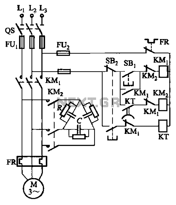
The circuit illustrated in Figure 3-151 consists of capacitor banks arranged in a specific configuration. Figure 3-151 (a) depicts capacitor banks connected in a shaped manner, which is suitable for use with shaped or Y-connected motors. Figure 3-151 (b)...
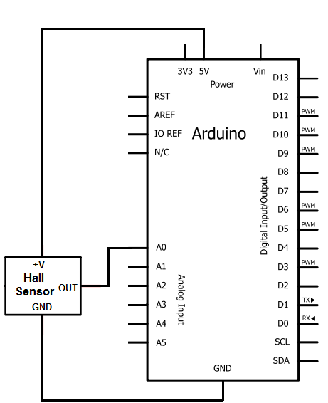
The Hall effect sensor utilized in this circuit is the A1302 Hall effect sensor manufactured by Allegro. This integrated circuit (IC) is capable of detecting magnetic fields. It will be connected to an Arduino, allowing the Arduino to read...
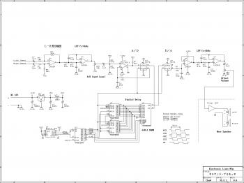
This is an easy-to-build surround sound processor circuit utilizing the digital delay processing method. This audio processor does not employ any specialized function integrated circuits that are difficult to obtain, and it is designed using only common-purpose integrated circuits....
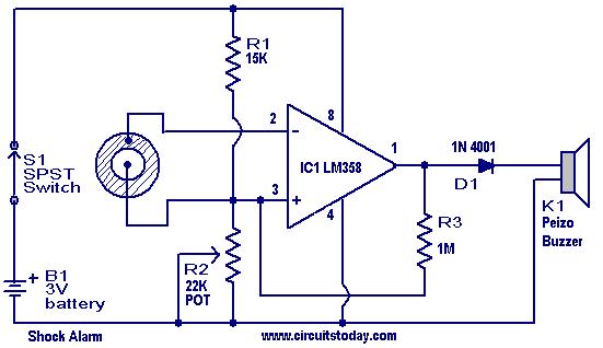
This is a simple shock-sensitive alarm circuit with numerous applications, ranging from home use to automobiles. The primary application of this circuit is as an anti-theft alarm for vehicles. A piezoelectric sensor is employed as the shock sensor and...
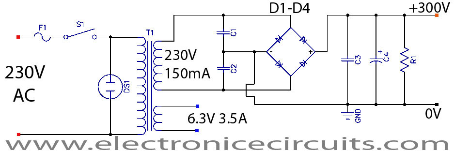
This is a successful vacuum tube project featuring a small amplifier where a 6V6GT output pentode is connected in triode mode, producing an output of approximately 4.5 watts. The project includes a single-ended audio amplifier with a resistive input...
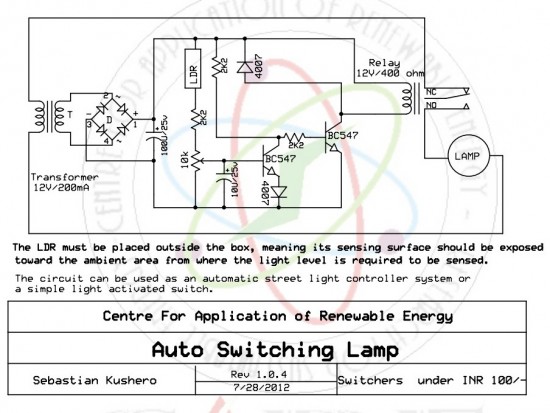
The circuit is designed to switch off a specific lamp or a group of lamps based on varying ambient light levels. Once constructed, it will turn off a lamp at dawn and turn it on at dusk. The power...