
Repeating Timer 4

The described circuit functions as a light-activated timer, designed to operate only during periods of low ambient light, such as nighttime. The core of the circuit is a light-dependent resistor (LDR) or phototransistor, which senses the intensity of light in the environment. When the light level falls below a predetermined threshold, set by the variable resistor, the timer circuit is triggered to initiate its operation.
The variable resistor, often referred to as a potentiometer, plays a crucial role in adjusting the sensitivity of the circuit. By altering its resistance, the user can fine-tune the darkness level required to activate the timer. This feature enhances the circuit's versatility, allowing it to be used in various applications, such as automatic outdoor lighting systems, security lighting, or garden lights that only turn on at dusk.
The circuit may include additional components such as a microcontroller or timer IC (e.g., 555 timer) to control the timing duration after activation. The output can be connected to a relay or transistor switch, which in turn controls the power to the load, such as a lamp or other lighting fixtures. The design ensures that the load remains off during daylight hours, thereby conserving energy and extending the lifespan of the lighting components.
In summary, this circuit effectively utilizes a light sensor and adjustable resistance to create a timer that operates exclusively during darkness, making it a practical solution for automated lighting control.This circuit is the opposite of Repeating Timer No.3. Its operation can be limited to the hours of darkness. Again - the variable resistor (preset) lets you choose the level of darkness at which the timer will begin to function.. 🔗 External reference
Related Circuits
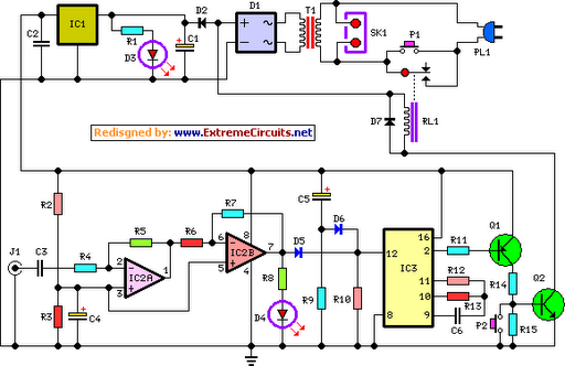
This device is a simple timer that keeps the headlights of a vehicle on for approximately 1 minute and 30 seconds, allowing access to dark areas without the need to manually switch off the lights. Activating switch P1 initiates...
This circuit deactivates an amplifier or any connected device when a low-level audio signal is absent at its input for at least 15 minutes. Activating switch P1 powers the device, enabling operation of any appliance connected to SK1. The...
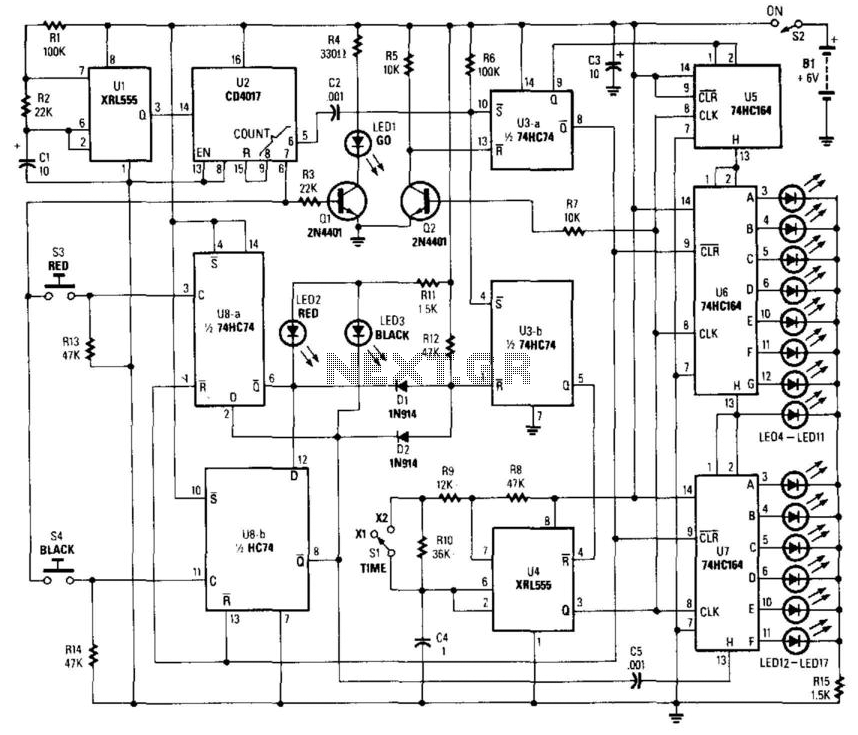
This circuit utilizes a timer to produce pulses at a 5-ms clock rate. The pulses are sequentially shifted into a shift register, illuminating an LED. An auxiliary timer generates one pulse per second to activate the "go" LED and...
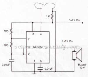
The circuit of a burglar alarm utilizing IC timer 555/556 functions as a security measure to prevent unauthorized entry into a premises. The alarm generates a loud sound when a thin wire connecting resistor R1 with pin 4 of...
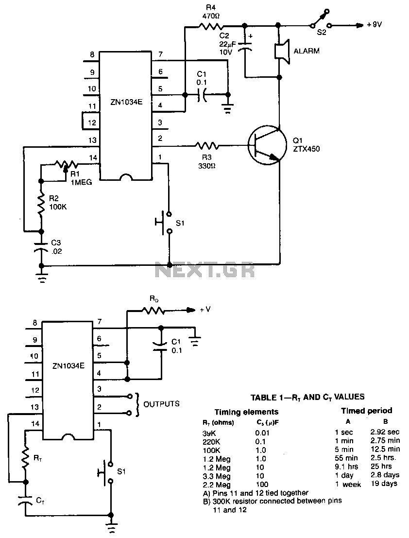
When used as a stand-alone device, the ZN1034E from Ferranti can provide timed intervals ranging from 1 second to 19 days, although the RC time constant is only 220 seconds. The ZN1034E includes an internal voltage regulator, an oscillator,...
This clock timer utilizes a PIC16F628 microcontroller to display a 3.5-digit time format and control an external load. It is programmable to time intervals from 1 to 59 minutes. The clock features a calendar that accounts for leap years...