
Replacing old capacitors
The overview of paper capacitors illustrates various types, where P1, P2, P3, and P4 are identified as poor quality, featuring glass bodies with tar sealing. P1 and P3 exhibit melted seals, with P1 losing its impregnating wax. P2 shows an unstuck tar seal, while P4 presents a swollen seal. P5, P6, and P7 represent paper capacitors that have maintained functionality.
The functionality and reliability of capacitors are critical in electronic circuits. Short circuits, open circuits, and leakage currents can significantly impact circuit performance. Identifying and addressing these issues is essential for maintaining the integrity of electronic equipment, especially vintage models where component aging is a common concern. Regular testing and maintenance can help prolong the lifespan of these components, ensuring optimal performance in various applications. Understanding the characteristics and failure mechanisms of different capacitor types aids in making informed decisions for repairs and replacements, ultimately enhancing the reliability of electronic systems.Original components, when still good, are stable and not subjected to infant mortality. Of course everybody has his own opinions derived from past experiences. Nevertheless answers may vary depending upon several reasons: quality of the design with proper use of right components, type and quality of materials, environmental conditions during life and storage of equipment. I see frequent discussions tied to specific models. Since almost every collector of old radio equipment may be interested in this topic, I decided to open a generic thread, hoping that readers would add their experiences. A short can be easily identified by low voltage and/or resistance values all around the faulty section.
Often shorted caps cause other faults, as burned resistors or blown fuses. Whenever one of the latter conditions is encountered, shorted capacitor should be suspected unless different cause is found. This failure is common in electrolytic capacitors, when fully dried. If faulty capacitor is in the B+ filter section, a loud hum will arise. In some circumstances, such as in the cathode path of audio power amplifier tubes, a dried capacitor could also give benefic effect on sound quality.
Opens can also be occasionally found in some polystyrene foil capacitors, due thermal stress on the leads. These may derive from different causes: partial drying of electrolyte in aluminum capacitors; drying or alteration of impregnating oils or waxes in paper capacitors; moisture adsorption in ceramic or in paper dielectric; small cracks in silver coating of some lacquered mica capacitors, partial chipping of ceramic capacitors.
A twenty-percent decrease in the capacitance of filter electrolytic capacitors may be tolerated, but a five-percent variation on the value of ceramic capacitors in tuned RF circuits may move resonance out of tuning range. A very high, but finite resistance value can be measured across any capacitor. In paper capacitors low resistance may be found because of moisture adsorbed by paper itself. Some leakage is acceptable in many circuits, as in decoupling paths of B+ distribution or in low voltage sections.
In other cases, as in the coupling between AF driver and AF power amplifier stage, leakage can move grid biasing of the power tube to positive values. In electrolytic capacitors leakage is due to small holes in dielectric oxide. Leakage current starts quite high when capacitors have been left inoperative for a long period. In this case, if full operating voltage is suddenly applied, leakage current may cause irreversible failures.
The dielectric layer can be easily repaired by a short reforming cycle. Paper foil Paper, usually impregnated with wax or oil, was used for general-purpose capacitors, ranging from about 1000 picofarads to over than 10 microfarads. It is still in use today, also in addition to plastic films, in many a. c. applications. Good paper capacitors stay still stable after over than 70 years. Some types or lots may give troubles in the years, due to poor hermetic sealing of their bodies, to poor manufacturing process or to unstable or hygroscopic impregnating fluids.
Pic. 1 Overview of paper capacitors. P1, P2, P3 and P4 are very poor types, with glass bodies and tar sealing. P1 and P3 show melted seals and P1 even lost its impregnating wax. P2 shows unstuck tar seal, P4 has swollen seal. P5, P6 and P7 are paper capaci 🔗 External reference
Related Circuits
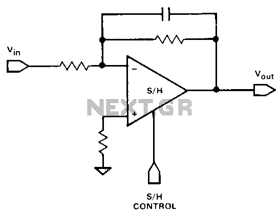
It is often necessary to filter a signal prior to sampling. This can be achieved using a single device. Any of the inverting or non-inverting filters that can be constructed with operational amplifiers (op-amps) may be utilized. However, it...
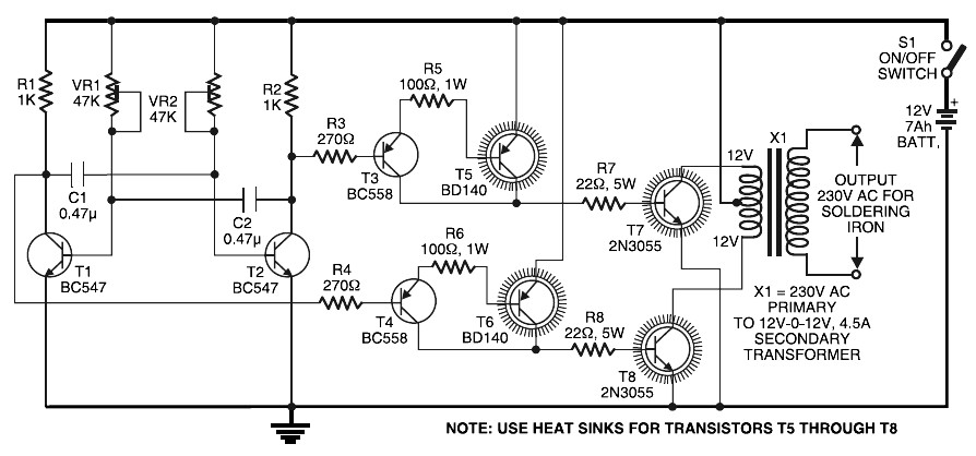
Simple Inverter for Soldering Iron. This is a straightforward and cost-effective inverter designed to operate small power soldering irons (25W, 35W, etc.) in the absence of mains supply. The circuit requires eight transistors along with several resistors and capacitors....
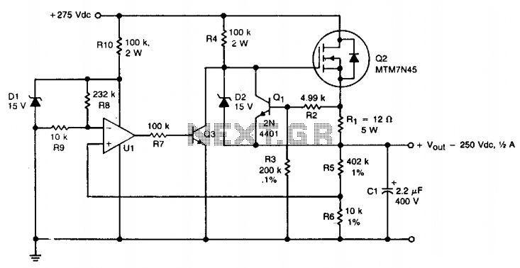
A TMOS MTM7N45 (Q2) is utilized as a series pass element in a linear high voltage supply that accepts +275 V unregulated and produces 250 V regulated with foldback current limiting. A 15 V zener diode (D1) provides the...

The microphone's capsule is believed to be a 32mm outer diameter (OD) design with a 26mm diaphragm and 3-micron membranes. It is most likely the standard Chinese-made 32mm K67 capsule commonly found in many inexpensive imported condenser microphones. The 32mm...
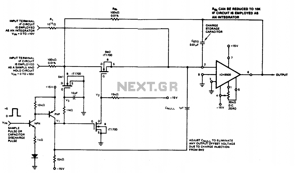
This circuit quickly charges capacitor CST0 to a voltage that matches an input signal. After charging, the input signal is electrically disconnected from the capacitor, allowing the charge to remain on CST0. Since CST0 is part of the negative...
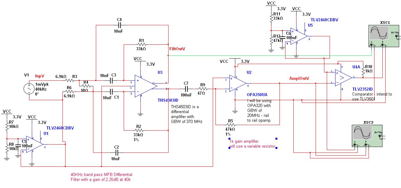
A circuit has been designed to detect the duration of an ultrasonic pulse as it travels a certain distance. The input signal is sourced from a 40 kHz ultrasonic receiver. The first stage consists of a 40 kHz band-pass...
Warning: include(partials/cookie-banner.php): Failed to open stream: Permission denied in /var/www/html/nextgr/view-circuit.php on line 713
Warning: include(): Failed opening 'partials/cookie-banner.php' for inclusion (include_path='.:/usr/share/php') in /var/www/html/nextgr/view-circuit.php on line 713