
Inverter circuit for soldering iron

This inverter circuit is designed to efficiently convert low-voltage DC power into high-voltage AC power suitable for various applications. The core of the inverter is the CMOS 4047 IC, which is configured as an astable multivibrator. This configuration allows for the generation of a square wave signal that oscillates at a frequency of either 50Hz or 60Hz, depending on the application requirements. The output from the 4047 is taken from pins 10 and 11, providing a symmetrical square wave that serves as the control signal for the power stage of the inverter.
The power amplification stage employs two 2N3055 transistors, which are capable of handling significant current, thus allowing the inverter to drive loads up to 60 watts. These transistors are configured in a push-pull arrangement, ensuring that they alternate in conducting the output to the transformer. The transformer steps up the voltage from 12V to the desired 220V AC output, making it suitable for powering various household appliances and tools.
MOSFET transistors, specifically the IRFZ44, are utilized in this design for their efficient switching capabilities. These devices are known for their low on-resistance and fast switching speeds, which contribute to the overall efficiency of the inverter. The primary winding of the transformer is connected to the outputs of the MOSFETs, allowing for effective energy transfer and voltage transformation.
The simplicity of this design, requiring only around 12 components, makes it an attractive option for hobbyists and engineers looking to create a low-cost inverter solution. The inverter can be powered from a standard 12V battery, such as those found in vehicles, making it versatile for outdoor or emergency applications. Additionally, the ability to power devices like electric razors, stroboscopes, and small fluorescent lamps highlights the practical utility of this inverter design in everyday scenarios.Simple Inverter for Soldering Iron. Right here is a very simple but low-cost inverter for making use of a small power soldering iron (25W, 35W, and so on) in the absence of mains supply. It requires eight transistors along with a number of resistors and capacitors. Transistors T1 and T2. This is a 60 Watts inverter circuit diagram which using a c ouple power transistor of 2N3055 for final amplification. Actually, the circuit is capable of driving medium loads of the order of 40 to 60 watts working with battery of 12V, 15 Ah or greater capacity. This inverter will convert. This simple inverter circuit 12VDC 220VAC contains a central part, the CMOS 4047, and converts a 12V DC voltage to 220V AC voltage.
The 4047 is applied as being a astable multivibrator. At pin 10 and 11 we obtain a rectangular symmetrically signal that is amplified by two Darlington. This DC to AC converter is very simple and contains no more than 12 components. IC CD4047 generates a signal with frequency 50/60Hz, who paraphase exits 10 and 11 is fed to the gates of MOSFET transistors IRFZ44. Transistors alternately commute primary winding of the transformer floor, and appears on. This is the small 12V inverter circuit. This inverter circuit could be utilized to power electric razors, stroboscopes and flash tubes, and small fluorescent lamps from a 12V vehicle battery.
In contrast towards the usual feedback oscillator type of inverter, the oscillator of this small 12V inverter is separate from. We aim to transmit more information by carrying articles. Please send us an E-mail to wanghuali@hqew. net within 15 days if we are involved in the problems of article content, copyright or other problems.
We will delete it soon. 🔗 External reference
Related Circuits
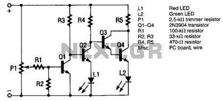
The monitor functions as a basic voltage comparator, utilizing a car battery as its power source. The input voltage to the comparator is adjusted using potentiometer PI. This adjustment ensures that the green LED L2 illuminates when the alternator...

This circuit utilizes a 4049 integrated circuit (IC) to control a 2N2222 switching transistor. The transistor, in turn, drives a piezo transducer known as crystal 1. The circuit design begins with the 4049 IC, which is a hex inverter capable...
The following circuit illustrates a timer circuit with independent mark and space periods. It is based on the 7555 integrated circuit (IC). The high output duration is calculated by T(on) = 0.7 Ra Ct, while the low output duration...
This code lock circuit is an electronic combination lock designed for daily use. It only responds to the correct sequence of four digits entered remotely. If an incorrect key is pressed, the lock resets. The lock code can be...
We are going to build a START-STOP drive (as commonly found in professional tools), that is a circuit with one switch to run the output (an LED in this case) and one switch to stop it. Nutchip feature two...

This circuit is used for a Digital Radar Speedometer. It allows for the measurement of the speed of any moving object, particularly vehicles such as cars. The speed is displayed in kilometers per hour (KPH) with a three-digit display....