
Restructuring of the pitch by the pitch selector circuit

The circuit design in Figure 4-13 employs a sophisticated tone control mechanism that allows for precise adjustments to the audio output. The use of operational amplifiers like the OP275 ensures that the circuit maintains high fidelity and low distortion, which is crucial for audio applications. The configuration of the tone control is such that it provides versatility in sound shaping, accommodating various user preferences for bass, midrange, and treble frequencies.
The inclusion of multiple switches (SAi, SA2, SA3, SA4, SA6, SA7, and SAg) enables the user to easily toggle between different tonal settings, enhancing the overall user experience. Each switch modifies the circuit's response by either introducing or bypassing specific components, thus allowing for tailored adjustments. For instance, the action of SAi not only connects capacitor C4 but also influences the overall tonal balance by managing bass and treble levels, which is essential for achieving the desired sound profile.
The circuit's ability to maintain a straight path for the audio signal when the straight distressed key is activated is particularly noteworthy. This feature preserves the integrity of the audio signal, making it ideal for situations where clarity and authenticity of sound are paramount. The design's adaptability to various operational amplifiers provides additional flexibility, allowing engineers and designers to customize the circuit based on availability and specific performance characteristics desired in their applications.
Overall, this tone control circuit exemplifies a well-engineered solution for audio signal processing, combining functionality with high-performance components to meet diverse acoustic requirements.Figure 4-13 is an adaptation of a common attenuated tone control from the pitch selector. It consists of two magnifications of each of the amplifiers 10, Icl used as a line amp lifier, l [C2 is used to compensate for attenuation o tone caused by networks in this circuit, the potentiometer still works, but the adjustment range than the narrow, it can be used to correct the frequency response curve of each file, in order to meet the needs of different people o in the circuit, when you press the language key, SAi, also deputy action, SAi make C4 access, bass is attenuated, Island makes the treble is bypassed, SA2 make Rj instead of R7, resistance increases, midrange gain is increased. When you press the concert button. SA3, SA4 action, SA3 rainbow effect with just the same, SA4 will c5 in parallel with the C4, while access circuit, high and low only for a small amount of lift o Press the orchestral key, SA6 action, R7 connected in parallel, the alkali resistance is small, midrange gain reduction, improved relatively high, bass o press bass is key, SA7, S} .e action, SA7 role and SA6 same tenor reduce, gb so clo .c11 series, capacity is reduced, treble attenuation, bypassing the island make midrange attenuation.
press the straight distressed key, SAg, SAio action, the whole tone disconnected from the network, the signal from the amplifier stage straight-line after a pass grade enlarge clamor, the sound signal remains original. The two circuits are assembled using high-performance op amp OP275, the circuit conversion rates up to 22V/Us, poles Voice good.
Can also be used QP249, or NE5532 also o
Related Circuits
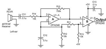
Assistance is required regarding the circuits provided below. The focus is on an ultrasonic receiver circuit that utilizes two ultrasonic components. The ultrasonic receiver circuit is designed to detect ultrasonic waves, typically in the frequency range of 20 kHz to...
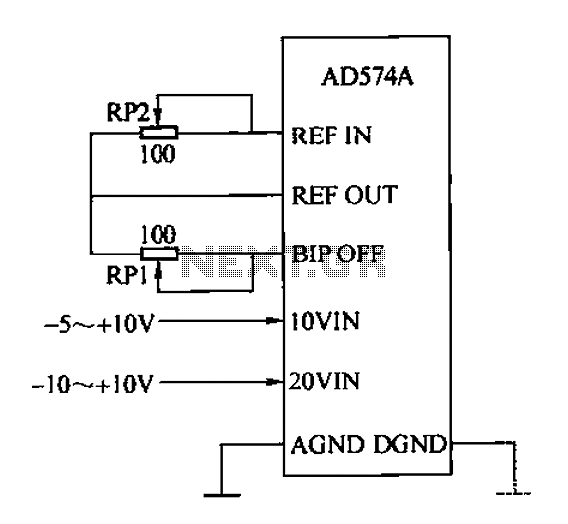
The AD574A is a high-performance 12-bit successive approximation analog-to-digital (A/D) converter that can interface directly with an 8 or 16-bit microprocessor bus. The input to the AD574A can be either unipolar or bipolar. The unipolar analog input voltage range...
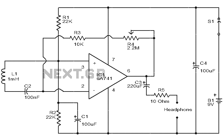
This is a simple circuit designed to detect electromagnetic radiation, including hidden wiring. It utilizes a 1mH inductor to sense the electric field. The induced voltage from the inductor is amplified by an operational amplifier (op-amp). An audio headset...
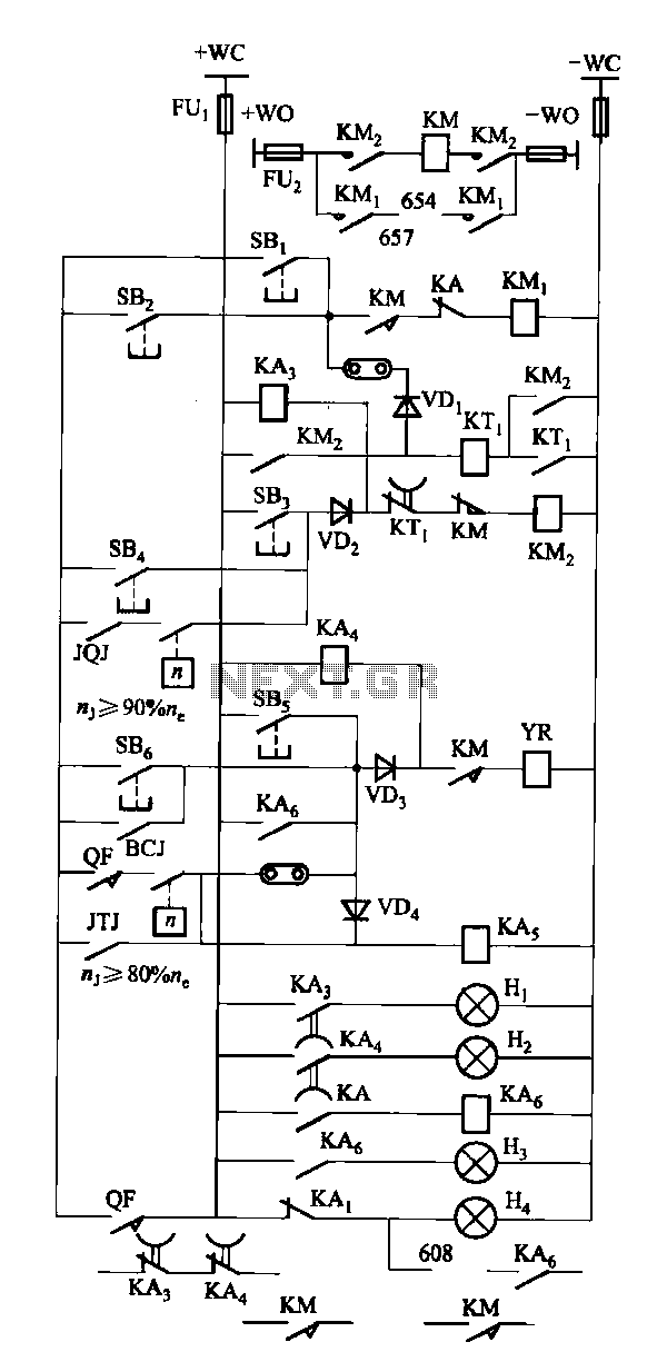
The FKL-32 type automatic thyristor excitation device is designed for synchronous generators with a terminal voltage of 400V and a capacity of 500kW and below. It is used for the automatic adjustment of excitation. The FKL-32 thyristor excitation device is...
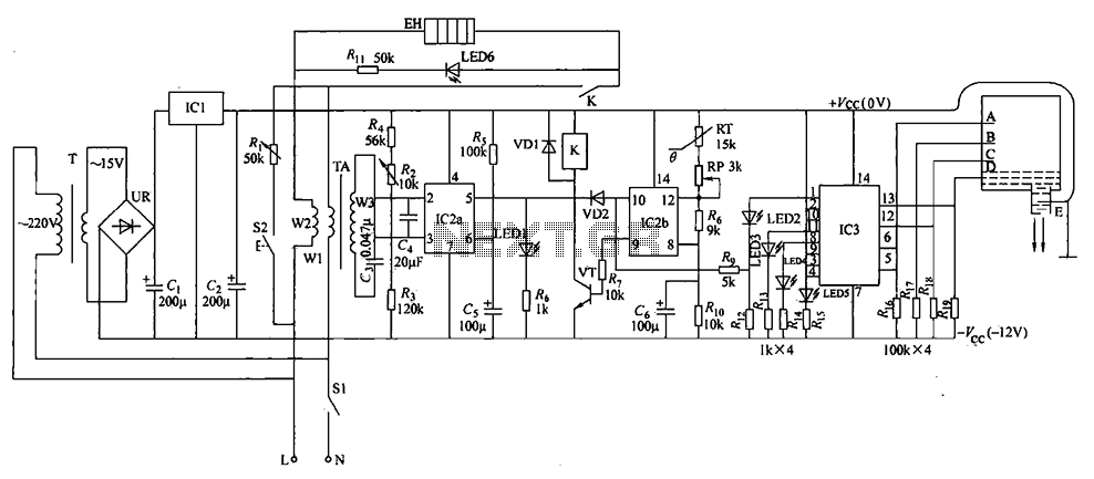
The electric water heater temperature control circuit includes functions for water level indication, temperature regulation, anti-dry protection, and automatic leakage power protection, ensuring safety and reliability. The circuit consists of a power circuit, leakage protection circuit, temperature control circuit,...
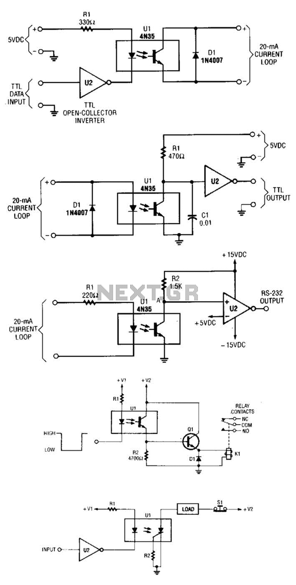
A circuit for isolating a variable resistor is presented. An optoisolator, which consists of an LED and a photo-conductive cell (or photoresistor), is utilized. The current flowing through the LED regulates its brightness, which subsequently dictates the resistance between...