
RF Digital Wattmeter

The circuit design incorporates an AD8307 logarithmic amplifier, which is adept at measuring power levels over a 50-ohm load. The 12-bit A/D converter is interfaced with the output of the AD8307, converting the analog voltage signal into a digital representation, with values ranging from 0 to 4095. The conversion process is crucial for obtaining accurate power readings in dBm, which is a standard unit of measurement in RF applications.
The look-up table approach streamlines the calculation of dBm values, eliminating the need for complex mathematical operations within the microcontroller. This method enhances the system's efficiency and response time, as the pre-calculated values facilitate rapid access to the corresponding text output based on the A/D converter's readings. Each output from the A/D converter directly indexes the memory where the relevant display text is stored, allowing for immediate retrieval and presentation on the display.
The use of EEPROM for storing the look-up table ensures that the system retains its configuration even after power loss. The choice of three 32k EEPROMs provides ample storage for the necessary data, while the programming process via RS232 simplifies the initial setup. The programming software automates the process, reducing the potential for human error and making it accessible for users without extensive technical expertise.
In terms of thermal management, the observations regarding the dummy load's temperature demonstrate the importance of understanding power dissipation in RF circuits. The ability to measure temperature in conjunction with power output provides valuable insights into the performance and reliability of the system.
Overall, the described circuit is a robust solution for measuring RF power, combining the precision of the AD8307 with an efficient digital processing system, ensuring accurate and reliable readings suitable for various applications in RF engineering.The power is measured by the circuit AD8307 over a 50 ohm dummy load. An A/D converter of 12 bit convert the analog output from the AD8307 to a digital number. Since the AD is a12 bit A/D you will have 4096 combinations. The output values will be from 0 to 4095. To calculate the power into dBm you need some mathematical calculations. I have solved this in a more simpel way, since it is a bit difficult to implement mathematic into the PIC. I use a look up table. It is memory bank containing all the display text. I have pre-calculated all the display text for each A/D value. The output values from the AD (0 to 4095) points to a direction in the memory where the actual display text value is stored.
The text will be fetched and presented on the display. I used a new HP 100MHz oscilloscope and I measured the amplitude over the 50 ohm dummy load. From the amplitude I then calculated the power. For month I was very dissapointed not to be able to generate more than 100mW output power. One day I burned up the dummy load totally. How is this possible with 100mW? I started to measure the temperature in the dummy load and then put DC into the dummy load. I increased the DC current until I reached the same temperature. What I noticed was that I had to put 3-5W into the dummy load to reach the same temp. The conclusion was simple to make: The oscilloscope should be run over by a truck or a tank! So I need a reliable Wattmeter. What every homebrewer should have is a wattmeter. A wattmeter use a 50 ohm dummy load and will present to you the energy into this load. The most widely used reference in RF systems is decibels above 1 mW in 50 ohm, written dBm. The advantage of using a memory map is that it will be easy to build, I can implement prefix in the text, It will be fast and it will work! In reality I will use 3 EEPROM of 32k. Totally I will use 98k. The EEPROM is cheap but there is one tricky thing to do. The memory table must be programmed into the EEPROM before it can be used. It is very important to hand program each byte manually to get it working. *smiling*...just joking! If you don't have a "manually programming unit" you can simply connect a RS232 cable to a computer and use the program I will support you with.
This program will handle everything, just start the program and go make yourself a cup of coffee. Every memory cell will take 10ms to burn so it will take 12-15min. Once the EEPROM has been programmed you will not have to do this again. There is a circuit AD8307specially made for this purpose and it has a very wide working range and is very easy to use. 🔗 External reference
Related Circuits
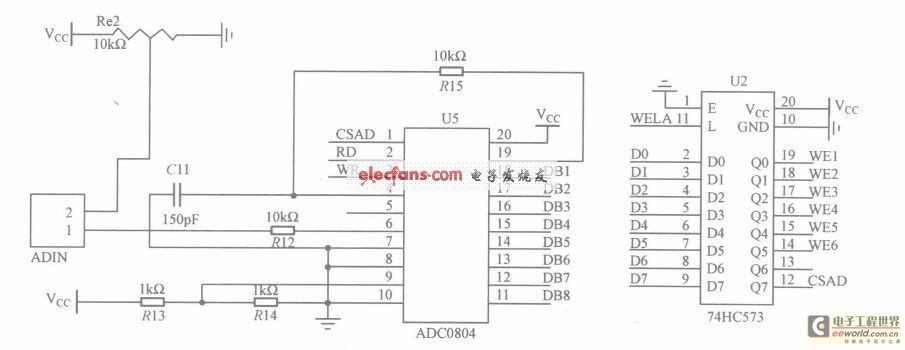
The circuit utilizes the ADC0804, which is configured for left-handed operation, alongside the 74HC573 latch, which is configured for right-handed operation. The latch is connected to a microcontroller, but they are not drawn in the same schematic. The CSAD...
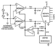
The Common Mode Rejection Ratio (CMRR) facilitates the rejection of high-frequency common-mode voltages, leading to the attenuation of elevated ambient noise levels from utility lines, industrial machinery, and other sources of radiation. The circuit diagram presented illustrates the advantages...
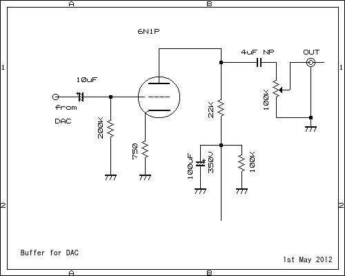
This pre-amplifier can be driven directly from the DAC. The described pre-amplifier is designed to interface directly with a Digital-to-Analog Converter (DAC). This direct connection allows for efficient signal amplification without the need for additional intermediary components, thereby simplifying the...
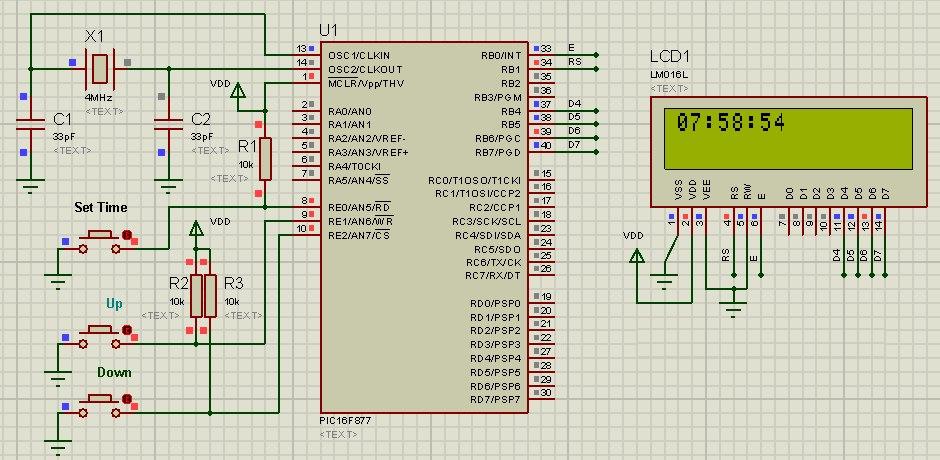
The PIC16 simulator (Proteus) allows for the verification of digital clock code, which can be modified as needed. Three push buttons are utilized to adjust the time. The code is written in C language using MPLAB with the HI-TECH...
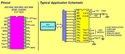
The circuit involves 8-bit, microprocessor-compatible analog-to-digital converters (A/D converters). It utilizes the ADC0804 chip for converting analog signals to digital form, in conjunction with an AT89C2051 microcontroller. The ADC0802 family consists of CMOS 8-bit, successive-approximation A/D converters that employ...
This circuit is a simple 8-bit analog-to-digital converter (ADC) that connects to a PC serial port. It utilizes the TLC548 A/D converter chip, which is known for its serial output. However, the output from the TLC548 is not directly...