
pic16f877 based controllable digital 25

The digital clock circuit utilizes a PIC16 microcontroller, which is programmed to manage timekeeping through the use of Timer0 for generating precise timing intervals. The timer is configured to trigger an interrupt every millisecond, enabling the microcontroller to maintain an accurate count of time. The msCounter variable serves to count these milliseconds, and upon reaching 1000, it signals the increment of the secCounter variable, effectively transitioning the count from milliseconds to seconds.
The clock's time-setting interface consists of three push buttons connected to designated pins on the microcontroller (RE0, RE1, RE2). The 'Set Time' button toggles the clock into a configuration mode, where the user can sequentially adjust the hours, minutes, and seconds. The blinking of the corresponding time value indicates which part of the time is currently being set. The Up and Down buttons facilitate the incrementing and decrementing of the selected time value, ensuring user-friendly interaction.
Furthermore, the LCD display is utilized to provide real-time feedback of the clock settings. It updates every second to reflect the current time, ensuring the user has a clear view of the clock's status. The logic governing the transitions between hours, minutes, and seconds is implemented using conditional statements that reset the counters appropriately once their maximum values are reached, maintaining a 24-hour format.
Overall, this digital clock circuit exemplifies an efficient use of microcontroller capabilities, timer interrupts, and user interface design to create a functional and adjustable timekeeping device.Using PIC16 simulator (Proteus) you can verify this digital clock code and change it according to your needs. Using three push buttons (As shown in figure below) you can adjust time as you desire. This code is written in C language using MPLAB with HI-TECH C compiler. You can download this code from the `Downloads`section at the bottom of this pag e. The above figure was taken after setting time to 07:58:54, timer0 is used as the base for digital clock generation. Timer0 is used here to generate 1msec interrupts. After every 1msec a global variable namedmsCounterincrements. WhenmsCounterreaches a value of 1000 then another global variable namedsecCounterincrements and this process repeats itself.
Similarly, whensecCounterreaches 60, then minCounterincrements. And whenminCounterreaches 60 thenhrCounterincrements. This process continues untilhrCounterreaches 24 then all of these variables reset their values. LCD is updated with the new values ofhrCounter, minCounterandsecCounterafter every second. You can set time using three push buttons attached onRE0, RE1andRE2pins (As shown in the above figure). By pressing `Set Time` button one time, code enters in configuration state. Hoursvalue starts to blink and you can modify it usingUpandDownbuttons. PressingUpbutton increments the value and pressingDownbutton decrements the value. When you are done settingHoursvalue, press`Set Time` button again, thenMinutesvalue will start to blink and you can adjust this value usingUpandDownbuttons.
Similarly, after setting Minutes value, you canpress`Set Time` button again, thenSecondsvalue will start to blink and you can adjust this value usingUpandDownbuttons. When you are done adjusting the time, then press`Set Time` button for the last time and this clock will start to work normally.
🔗 External reference
Related Circuits

The core component of this digital volume controller (DVC) circuit is the IC2 4067, which is a 16-channel analog multiplexer. A 1kΩ resistor is connected between each input and output, allowing the multiplexer to function similarly to a potentiometer....
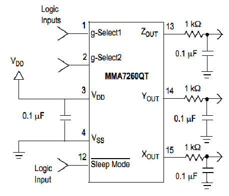
Microcontroller-Based Accelerometer Project. Just as a speedometer is a device that measures speed, an accelerometer is a device that measures acceleration. The microcontroller-based accelerometer project utilizes an accelerometer sensor to detect changes in velocity and orientation. This project typically involves...
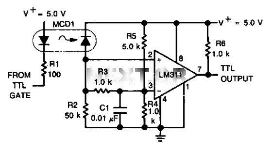
An optoelectronics device is utilized to couple a digital (TTL) signal to another system. The photodiode within the optocoupler drives an LM311 configured to generate a TTL-compatible output. This configuration is particularly beneficial in scenarios where grounds cannot be...
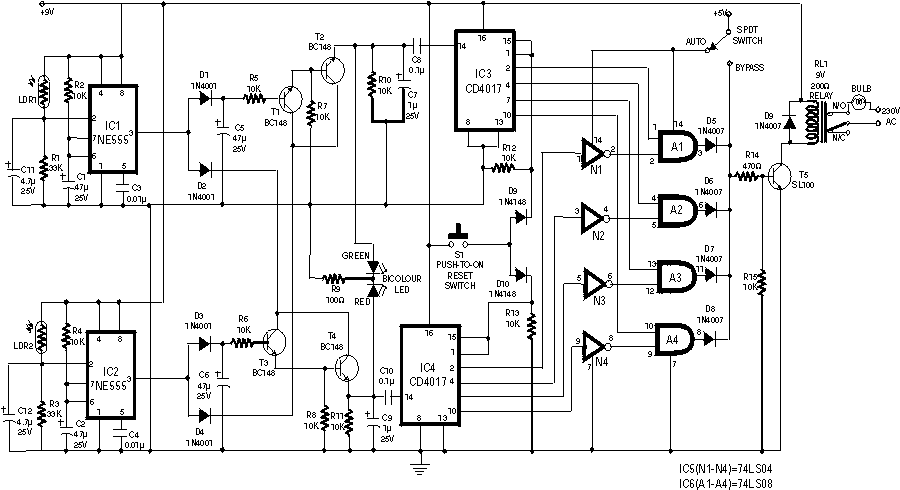
The following circuit illustrates the sensor circuit diagram for automatic room lights. This circuit is based on the CD4017 integrated circuit (IC) and features the use of two light-dependent resistors (LDRs). The automatic room light circuit utilizes the CD4017 decade...
This circuit provides a visual 9 second delay using a 7 segment digital readout LED. When the switch is closed, the CD4010 up/down counter is preset to 9 and the 555 timer is disabled with the output held high....
A micro power supply unit (PSU) is designed to power a breadboard with a voltage output of 5 volts. It can be connected to a 9V battery, a 12V source, or any other direct current (DC) power supply ranging...