
RF field strength meter

This Field Strength Meter circuit operates on the principle of RF signal detection and conversion into a readable DC output. The small antenna is designed to capture electromagnetic waves within the desired frequency range, specifically tuned to 2.4 GHz for Wi-Fi applications. The germanium diode (1N60) serves as the detector, converting the RF signal into a DC voltage. The low threshold voltage of the diode ensures that even weak signals can be detected effectively.
The capacitor (1 nF) works in conjunction with the diode to filter out high-frequency noise, allowing for a smoother DC signal to be amplified. The 100 kΩ resistor, which is planned for future inclusion, will help set the gain of the circuit and improve the overall sensitivity. The use of a Vu-Meter as an indicator provides a clear visual representation of the detected RF activity, making it easier to observe fluctuations in signal strength.
The circuit's power supply, a 9 V battery, ensures adequate voltage for operation while maintaining portability. The careful design of the antenna, including the impedance matching resistor, is crucial for optimizing performance and ensuring accurate readings across the intended frequency range. The versatility of this circuit allows it to serve multiple purposes, from monitoring Wi-Fi activity to detecting potential microwave leakage, making it a valuable tool for both hobbyists and professionals in the field of electronics.A very simple Field Strength Meter composed of a small antenna, a detector diode, a resistor, capacitor and a Micro Ammeter. Assuming that this simple circuit would be sensitive enough to detect the HF field, providing we keep it close enough to the transmitting antenna.
This worked quite well, and the intermittent problem was easily diagnosed and fixed; it was caused by a broken antenna cable, making intermittent contacts. With the meter we were able to see a clear drop of the field strength when moving the cable. From there, the technical curiosity took over; what if we could improve the circuit, making it more sensitive and, how high in frequency it would still work Would it work for much higher frequencies such as 2. 4 GHz, to check RF fields from Wi-Fi routers and mobile phones I gave up (at least temporarily!) to the idea of building a wide range RF amplifier to amplify the antenna signal over that wide range of frequencies.
This might be another project for another rainy Sunday (or many more rainy Sundays!). Instead, I preferred trying to amplifying the DC signal after the RF detection and see how far we can go. And here we go; we have a very simple instrument that can detect the activity of your Wi-Fi router, your mobile phone and about any RF transmitter through a wide range of frequencies.
It is powered by a 9 V battery. The diode is a critical component; it should have a low threshold voltage. The diode used in this circuit is a germanium diode 1N60. A ghost from the past, but it is still available on the market (Escol for example). The diode and the 1 nF capacitor are soldered directly at the base of the antenna connector. In the next version of this circuit I would put the 100 K resistor there as well. Another critical point is the antenna. It should be cut to wavelengths for the frequency range you want to measure. In this project the antenna was cut to around 3cm length (1/4 wavelength at 2. 4 GHz). I soldered a 50 Ohm resistor at the base of the antenna for matching the impedance (Well a 47 Ohm was close enough!). This simple RF Field Strength Meter proved to be much more effective than expected. It will react to your Wi-Fi router and mobile phone transmitting activities. You can also check the leaks of your microwave hoven, but be careful, put the sensitivity button to a very low position as the signal proved to be very strong!
I guess this is normal This project can be built with components we have in our drawers. Who want to go out buying components on a rainy Sunday I used a Vu-Meter from a scrapped amplifier for the indicator. The scale is not important as the measurements are comparative anyway. Those Vu-Meters are quite sensitive. The OP Amp can be any one of the common type as we amplify DC only. I used one fond in a drawer 🔗 External reference
Related Circuits
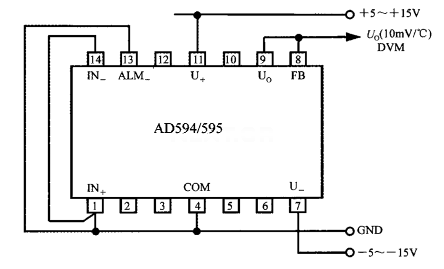
The AD594/595 can be configured to measure temperature in Celsius. In the circuit diagram, the IN+ and IN- terminals should be shorted to the COM terminal. The output voltage (Uo) has a temperature coefficient of 10 mV/°C, which can...
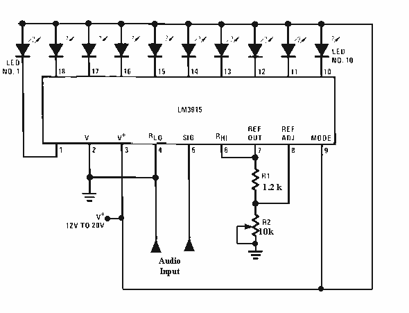
The LM3915 is a monolithic integrated circuit that senses analog voltage levels and drives ten LEDs providing a logarithmic 3 dB/step analog display. LED current drive is regulated and programmable, eliminating the need for current limiting resistors. More: This...
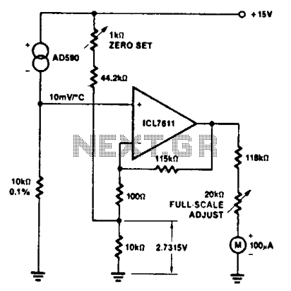
The ultra-low bias current of the ICL7611 enables the use of large-value gain resistors, maintaining meter current error below a specified percentage, thus eliminating the need for an additional meter-driving amplifier. The ICL7611 is a precision analog-to-digital converter (ADC)...
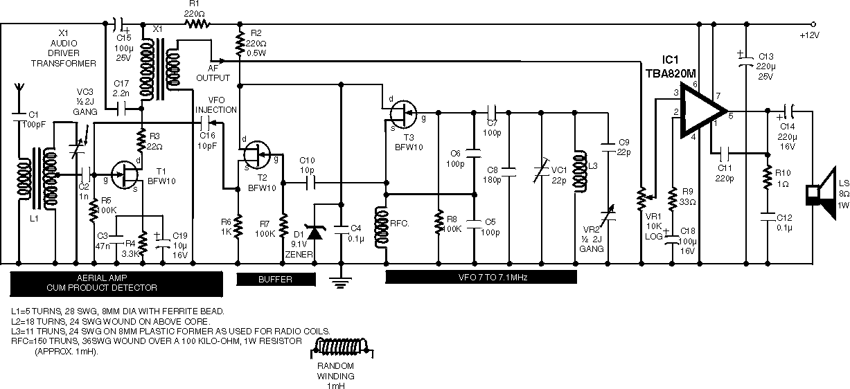
Using the circuit of 40-metre band direct-conversion receiver described here, one can listen to amateur radio QSO signals in CW as well as in SSB mode in the 40-metre band. The circuit makes use of three n-channel FETs (BFW10)....
The use of diode rectifiers in AC voltmeters with a low lower limit of measurement range (0.5-1 V) leads to significant nonlinearity of the scale due to the nonlinearity of the current-voltage characteristics of diodes. The incorporation of electronic...
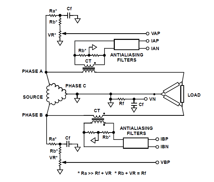
How can a circuit be built for digital readout of three-phase power consumption in a home using a chip like ADE7762? There is an interest in polyphase energy metering. To construct a circuit for digital readout of three-phase power consumption...