
Thermocouple cold junction compensator AD594 595 centigrade thermometer circuit diagram

The AD594 and AD595 are precision temperature sensors that provide a linear output voltage proportional to the temperature in degrees Celsius. To utilize these devices effectively, the circuit configuration requires that the IN+ and IN- terminals be connected to the common (COM) terminal. This configuration ensures that the sensor operates within its designed parameters, allowing for accurate temperature readings.
The output voltage, Uo, generated by the sensor is linearly related to the temperature, with a temperature coefficient of 10 mV/°C. This means that for every degree Celsius change in temperature, the output voltage changes by 10 mV. This linear relationship facilitates straightforward calculations when interfacing with measurement devices.
To measure the output voltage accurately, a digital voltmeter (DVM) is employed. The DVM converts the analog voltage signal from the AD594/595 into a digital format, allowing for easy reading of the temperature value. It is important to ensure that the DVM is calibrated and has sufficient resolution to display the temperature readings accurately.
In summary, the AD594/595 temperature measurement circuit is a simple yet effective solution for monitoring temperature in Celsius. The proper configuration of the IN+ and IN- terminals with respect to the COM terminal is crucial for accurate measurements, and the output voltage's linear relationship with temperature simplifies the process of obtaining and displaying temperature values.AD594/595 can also be configured to Celsius, the circuit shown in FIG. This time should be IN +, IN- terminal and COM shorted, the output voltage Uo temperature coefficient of 10mV/, can be sent to the DVM to measure and display the temperature value.
Related Circuits

This simple circuit produces a beeping sound that lasts for approximately 3 seconds whenever a whistle is made. The CMOS Hex inverter CD4049 serves as the core component of this circuit. Among the six inverters in the CD4049, U1a...
A buzzer circuit utilizes a PIC microcontroller to drive a piezo buzzer. The microcontroller is a low-power processor that is ideal for portable and compact devices where battery conservation is essential. The buzzer circuit employs a PIC microcontroller, which serves...
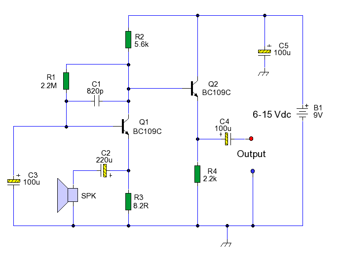
This circuit enables the use of an inexpensive loudspeaker as a microphone. Sound waves that reach the speaker cone create fluctuations in the voice coil. The movement of the voice coil within the speaker's magnetic field generates a small...

This design circuit is intended for sine wave oscillators, providing both sine and square wave outputs across a frequency range from below 20 Hz to above 20 KHz. The oscillation frequency can be easily adjusted by changing a single...

An LED flasher circuit can be constructed using a 555 integrated circuit (IC). The use of the 555 IC allows for greater flexibility in adjusting the flashing rate of the LED. This LED flasher circuit is similar to other...
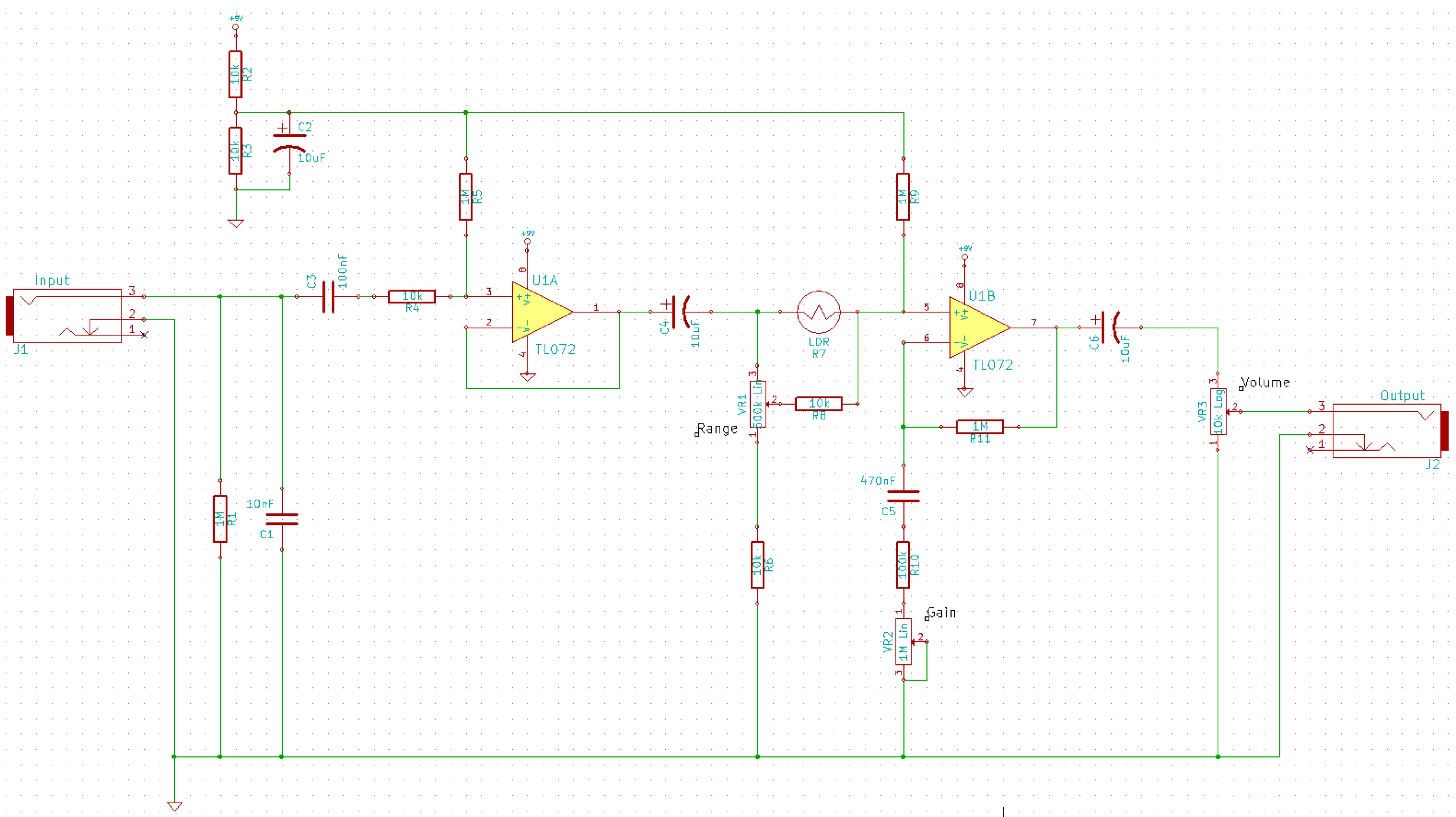
This is a simplified schematic for the Solar Lifeforce. The design eliminates the expression/CV output features and the toggle for the buffer, making it a straightforward circuit. It may benefit from adding small capacitors between R5 and ground, as...