
Rf power meter

The reflectometer, also known as a standing wave ratio (SWR) power meter, is an essential instrument used in RF applications to measure the efficiency of power transfer from a source to a load. It assesses the reflected power in relation to the incident power, providing a critical parameter for evaluating antenna performance and matching circuits.
The circuit design typically includes a directional coupler, which samples the forward and reflected power. The directional coupler can be implemented using transmission line techniques or ferrite-based components, ensuring minimal insertion loss across the specified frequency range. The output of the coupler feeds into a power detector, which converts the RF power levels into a proportional DC voltage. This voltage is then processed by a microcontroller or analog circuitry to calculate the SWR.
For low-power applications (500 mW), components such as low-power RF transistors or operational amplifiers can be utilized to maintain accuracy and efficiency. In contrast, for high-power applications (up to 500 watts), robust components are required, including high-power resistors and specialized RF connectors to handle the increased load without overheating or failure.
Calibration of the reflectometer is crucial for accurate measurements. It typically involves using known loads (like short circuits and open circuits) to establish reference points for the SWR readings. Additionally, the design may incorporate a display unit, either analog or digital, to provide real-time feedback to the user.
Overall, the reflectometer serves as a vital tool in RF engineering, aiding in the optimization of transmission lines, antennas, and other RF components by ensuring that power is efficiently transmitted with minimal reflection.Reflectometer (SWR Power Meter) covers three decades—from 100 kHz to 100 MHz It can be constructed for rf powers as low as 500 mW or up to 500 watts.
Related Circuits
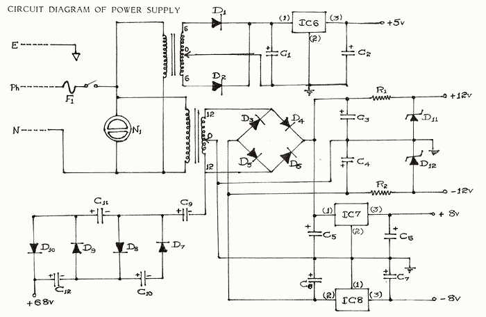
Every electronic device primarily requires a DC power supply for operation. This is a fundamental requirement for any construction project. Consequently, there is a need to obtain multiple voltage values for cost efficiency, convenience, and compact arrangement in various...
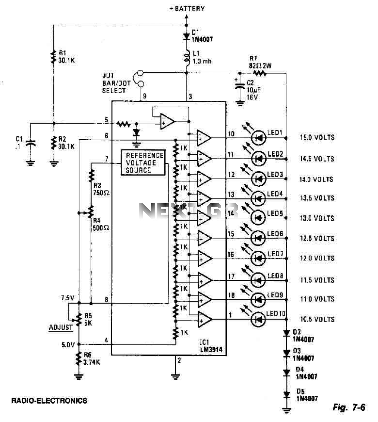
This screen utilizes ten LEDs to indicate a voltage range from 10.5 to 15 volts, with each LED corresponding to a 0.5-volt increment. The core component of the circuit is the LM3914 LED bar graph/display driver. A trimming potentiometer,...
.gif)
This circuit utilizes a single integrated circuit (IC) along with a minimal number of external components to display audio levels through ten LEDs. The input voltage range is from 12V to 20V, with a recommendation for 12V. The LM3915...
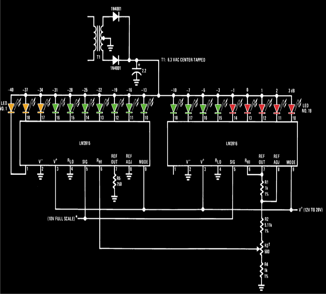
A VU meter, or volume unit meter, is a device used to indicate the music volume output from an amplifier or loudspeaker system. It can also be viewed as a device for displaying the PMPO (Peak Music Power Output)...
A circuit for a bicycle horn utilizing a low-cost telecom ringer chip is presented. This design can be powered by a bicycle dynamo, eliminating the need for frequently replaced batteries. The circuit includes a half-wave voltage-doubler section formed by...
Typically, most Japanese motorcycles do not have a charge control lamp at all, and even on bikes equipped with such a lamp (like the Bosch system used in BMW and Moto Guzzi), defects may still occur, causing the "idiot...